www.ti.com
Schematic
5
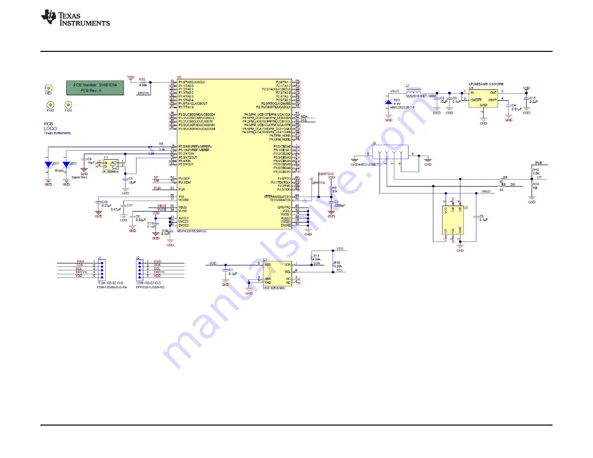
Figure 54. HDC1050EVM Schematic
39
SNAU181A – June 2015 – Revised June 2015
HDC1050EVM User 's Guide
Submit Documentation Feedback
Copyright © 2015, Texas Instruments Incorporated
Страница 1: ...HDC1050EVM User s Guide User s Guide Literature Number SNAU181A June 2015 Revised June 2015...
Страница 2: ...430F5528 microcontroller C as well as the HDC1050 The C is used to control the HDC1050 and communicate with a host PC through a USB port The EVM is designed to be broken into two sections if desired T...
Страница 3: ...e PC and provides power for the EVM 2 2 Hardware Setup The HDC1050EVM power is supplied via the USB connector The LDO U4 converts the 5V from the USB to 3 3V used by the HDC1050 and the MSP430 The EVM...
Страница 4: ...the EVM tool page 2 Extract the downloaded ZIP file 3 Run the included executable 4 Follow all directions from the installer Figure 2 GUI Installer Welcome Page 5 Read the license agreement and if you...
Страница 5: ...are is not a system administrator a directory not with Program Files should be chosen instead of the default Figure 4 GUI Installer Installation Directory 7 Wait for all files to install 5 SNAU181A Ju...
Страница 6: ...iver choose to install the driver anyways If running Windows 8 or 8 1 the PC must be started in a Safe mode to install the unsigned driver Figure 6 EVM Driver Installer Welcome Page 9 Wait for the dri...
Страница 7: ...ish after the driver has been installed Figure 8 EVM Driver Installer Complete 11 Click Finish to complete the software installation 7 SNAU181A June 2015 Revised June 2015 HDC1050EVM User s Guide Subm...
Страница 8: ...Setup www ti com Figure 9 GUI Installer Complete 8 HDC1050EVM User s Guide SNAU181A June 2015 Revised June 2015 Submit Documentation Feedback Copyright 2015 Texas Instruments Incorporated...
Страница 9: ...ed through the connectors J1 and J2 and a 4 wire cable In this configuration the thermal mass of the EVM is dramatically reduced improving the temperature measurement performance of the HDC1050 The ca...
Страница 10: ...use the GUI 3 1 Starting the GUI Follow these steps to start the GUI 1 Select the windows start menu 2 Select All programs 3 Select the Texas Instruments folder 4 Select the Sensing Solutions GUI 5 Cl...
Страница 11: ...igure 14 GUI Introduction Page 3 2 Connecting the EVM Follow these steps to connect the EVM to the GUI 1 Attach the EVM to the computer via the USB port 2 The GUI always shows the connection status on...
Страница 12: ...irtual machines may be used or multiple PC s are required Future releases will support multiple EVMs from a single instance of the GUI Figure 15 GUI Disconnected From EVM Figure 16 GUI Connected from...
Страница 13: ...GUI follow these steps 1 Click Menu in the upper left corner Figure 17 GUI Menu Button 2 Select the desired page from the menu shown on the left 13 SNAU181A June 2015 Revised June 2015 HDC1050EVM Use...
Страница 14: ...se this page to read the currect register values on the device 3 4 1 Automatically Updating GUI Register Values Using Auto Read Autoread will periodically request the register values on the device Cli...
Страница 15: ...r change a single bit within the register The recommended update mode is always Immediate and not Deferred To update register values follow these steps 1 Double click the current value of the register...
Страница 16: ...into the box and click enter The text box changes to normal text and the GUI will send a command to the EVM to update the device register Figure 21 Entering New Value for Register on Register Page 16...
Страница 17: ...it values rather that entire register values follow these steps 1 Hover the mouse over the desired bit to change Figure 23 Hovering Mouse Over Register Bit Value on Register Page 17 SNAU181A June 2015...
Страница 18: ...ster Bit Value on Register Page 3 4 3 Reading Register Values without Auto Read To read register values follow these steps 1 Select the register to update by clicking any column of the register row in...
Страница 19: ...ter button to update the selected register s current value and bit values in the table Figure 26 Reading the Current Device Register Value on Register Page 19 SNAU181A June 2015 Revised June 2015 HDC1...
Страница 20: ...the button immediately right to the Auto Read selection dropdown Figure 27 Save Register Values to File on Register Page 2 Choose a JSON file name and the directory to save it within Then click Save 2...
Страница 21: ...d Device Configuration To load previously saved register settings from a JSON file follow these steps 1 Click the button furthest right from the Auto Read selection dropdown 21 SNAU181A June 2015 Revi...
Страница 22: ...e on Register Page 2 Select the JSON file with the desired settings and click Open Figure 30 Selecting Previously Save Register Value JSON File 22 HDC1050EVM User s Guide SNAU181A June 2015 Revised Ju...
Страница 23: ...The Sensing Solutions GUI and EVM provide a tool to capture measurement data at rates up to 500Hz The section describes how to use the data measurement tools from the Data Streaming page accessible f...
Страница 24: ...ative humidity boxes shown next to the graph units Selecting or not selecting the data types only affects the graph and not the data logged to a file If a data type is not enabled in the Configuration...
Страница 25: ...ming Graph Showing Only Relative Humidity Percent Figure 34 Data Streaming Graph Showing Only Temperature 25 SNAU181A June 2015 Revised June 2015 HDC1050EVM User s Guide Submit Documentation Feedback...
Страница 26: ...upper right under next to Click to Select Log File Figure 35 Select Log File Button on Data Streaming Page 2 Select a file name and directory to save the data to and then click the Save button 26 HDC1...
Страница 27: ...rtical axis scale and sampling rate To set the vertical axis scale or change the sampling rate follow these steps 1 Click the Show Graph Configuration button 27 SNAU181A June 2015 Revised June 2015 HD...
Страница 28: ...Sampling Rate table Note that the GUI sampling rate affects only the graph and logging rate but not the actual device sampling rate Figure 38 Setting the Data Streaming Sample Rate to 1 Second 28 HDC1...
Страница 29: ...Vertical Scaling table Figure 39 Manually Setting the Vertical Scale on Data Streaming Graph 3 6 4 Starting and Stopping Measurement Data Acquisition To start data streaming click the Start button 29...
Страница 30: ...ta Streaming Graph Figure 41 Data Acquisition In Progress on Data Streaming Page To stop data streaming click the Stop button 30 HDC1050EVM User s Guide SNAU181A June 2015 Revised June 2015 Submit Doc...
Страница 31: ...Streaming Graph 3 6 5 Displaying Measurement Data Statistics Click the Show Statistics button to view the measurement statistics 31 SNAU181A June 2015 Revised June 2015 HDC1050EVM User s Guide Submit...
Страница 32: ...how Statistics Button on Data Streaming Graph Figure 44 Data Statistics on Data Streaming Graph 32 HDC1050EVM User s Guide SNAU181A June 2015 Revised June 2015 Submit Documentation Feedback Copyright...
Страница 33: ...stream the number of data samples displayed can be selected by moving the dual slider under the graph Figure 45 Moving the Data Graph Sample View 33 SNAU181A June 2015 Revised June 2015 HDC1050EVM Us...
Страница 34: ...are To upload new firmware to the EVM navigate to the Firmware page from the GUI menu and follow these steps 1 Click the button to select a TI TXT firmware file 34 HDC1050EVM User s Guide SNAU181A Jun...
Страница 35: ...Firmware Upload Page 2 Select the firmware file and click Open Figure 48 Selecting TI TXT Firmware File for Upload to EVM 35 SNAU181A June 2015 Revised June 2015 HDC1050EVM User s Guide Submit Docume...
Страница 36: ...upload Do NOT disconnect the EVM from the PC at this time Also note that the GUI will disconnect from the EVM The upload process should not take more than one minute Figure 50 Firmware Upload in Progr...
Страница 37: ...www ti com GUI Operation Figure 51 Firmware Upload Success 37 SNAU181A June 2015 Revised June 2015 HDC1050EVM User s Guide Submit Documentation Feedback Copyright 2015 Texas Instruments Incorporated...
Страница 38: ...the EVM but in most system designs should be left floating not contacted with GND to reduce the influence of the PCB thermals on the temperature measurement Figure 52 Top Layer Routing Figure 53 Botto...
Страница 39: ...w ti com Schematic 5 Schematic Figure 54 HDC1050EVM Schematic 39 SNAU181A June 2015 Revised June 2015 HDC1050EVM User s Guide Submit Documentation Feedback Copyright 2015 Texas Instruments Incorporate...
Страница 40: ...mount FID1 FID2 FID3 Fiducial10 20 3 TSW 105 07 G S Header TH 100mil 5x1 Gold plated 230 mil J1 J2 TSW 105 07 G S 2 above insulator 48037 2200 Connector USB Type A 4POS R A SMD J3 CONN_USB_0480 1 372...
Страница 41: ...A Revision Page Added content on new GUI operation 10 NOTE Page numbers for previous revisions may differ from page numbers in the current version 41 SNAU181A June 2015 Revised June 2015 Revision Hist...
Страница 42: ...ing the warranty period to the address designated by TI and that are determined by TI not to conform to such warranty If TI elects to repair or replace such EVM TI shall have a reasonable time to repa...
Страница 43: ...transmitter has been approved by Industry Canada to operate with the antenna types listed in the user guide with the maximum permissible gain and required antenna impedance for each antenna type indic...
Страница 44: ...ified allowable ranges some circuit components may have elevated case temperatures These components include but are not limited to linear regulators switching transistors pass transistors current sens...
Страница 45: ...REMOVAL OR REINSTALLATION ANCILLARY COSTS TO THE PROCUREMENT OF SUBSTITUTE GOODS OR SERVICES RETESTING OUTSIDE COMPUTER TIME LABOR COSTS LOSS OF GOODWILL LOSS OF PROFITS LOSS OF SAVINGS LOSS OF USE L...
Страница 46: ...sponsible for compliance with all legal regulatory and safety related requirements concerning its products and any use of TI components in its applications notwithstanding any applications related inf...