Hardware Description and Setup
3
SNLU222B – December 2016 – Revised September 2019
Copyright © 2016–2019, Texas Instruments Incorporated
FPC401 and FPC402 Evaluation Module (EVM) User’s Guide
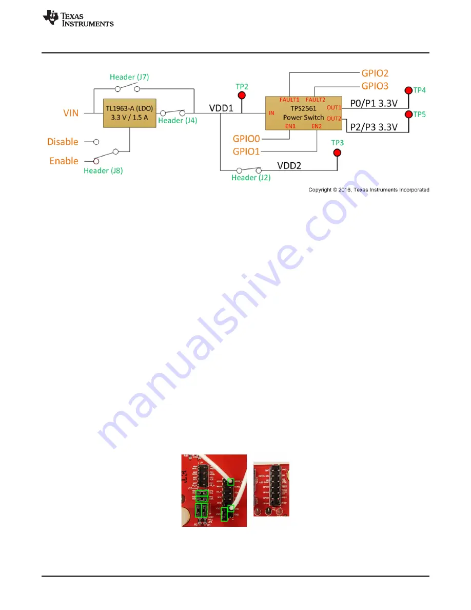
Figure 2. Power Block Diagram – Configured for LDO Use
1.2
Communication Protocol Configuration
The following sections describe how to configure the FPC401EVM and FPC402EVM for I2C and SPI
protocols.
1.2.1
I2C Configuration
For I2C communication with the onboard MSP430, refer to
and configure the board based on the
following procedure.
1. Leave the PRTCL_SEL pin disconnected (header J3).
2. Connect the MSP430 SCL and SDA to the FPC SCL and SDA through header J12. The SPI header
(J9) should be disconnected.
3. Connect the 2.7-k
Ω
pullup resistors through header J1.
4. Connect the VDD2 pin to the VDD1 pin through header J2.
5. Connect the ADDR_N pin to GND through header J2 with the provided jumper wire.
For I2C communication with an external host controller, disconnect the MSP430 SDA and SCL. Connect
the FPC SDA and SCL pins to the SDA and SCL pins of the host controller. Only connect the onboard
pullup resistors if the host board does not have pullups.
To control multiple EVMs, connect all the SDA and SCL pins together. Only one board should have the
MSP430 and pullup resistors connected to these pins. The ADDR_N of the first device should be tied to
GND as shown in
. Connect DONE_N pin of the first device to the ADDR_N of the second
device, and the DONE_N pin of that device to the following device in a daisy-chained fashion until all
ADDR_N pins are connected. Connect the final DONE_N pin to GND. See the data sheet for more details
on how I2C is configured.
Figure 3. I2C Configuration


