


Setup
Table 4. J5 Pin Out
Pin
Description
J5.1
Not Connected
J5.2
SHLD1
J5.3
CIN1
J5.4
Not Connected
J5.5
SHLD1
J5.6
Not Connected
J5.7
Not Connected
J5.8
Not Connected
J5.9
Not Connected
J5.10
Not Connected
2.3
HW Setup
The power supply of FDC1004Q is provided by the LDO (U4), which is sourced from the USB 5.0V. The
I2C communication with FDC1004Q is fully managed by the MSP430F5528IRGC microcontroller (U3).
The FDC1004Q has a fixed I2C address.
2.4
SW Setup
Ensure that the FDC1004QEVM GUI and the drivers have been installed on the host computer. Plug the
EVM into an available USB port on the host.
2.5
Operation
Plug the EVM into the host computer. The host computer should automatically detect the device as an
EVM. Launch the GUI and configure the desired data acquisition mode for FDC1004Q. Then, it should
automatically start measuring on the configured sensors.
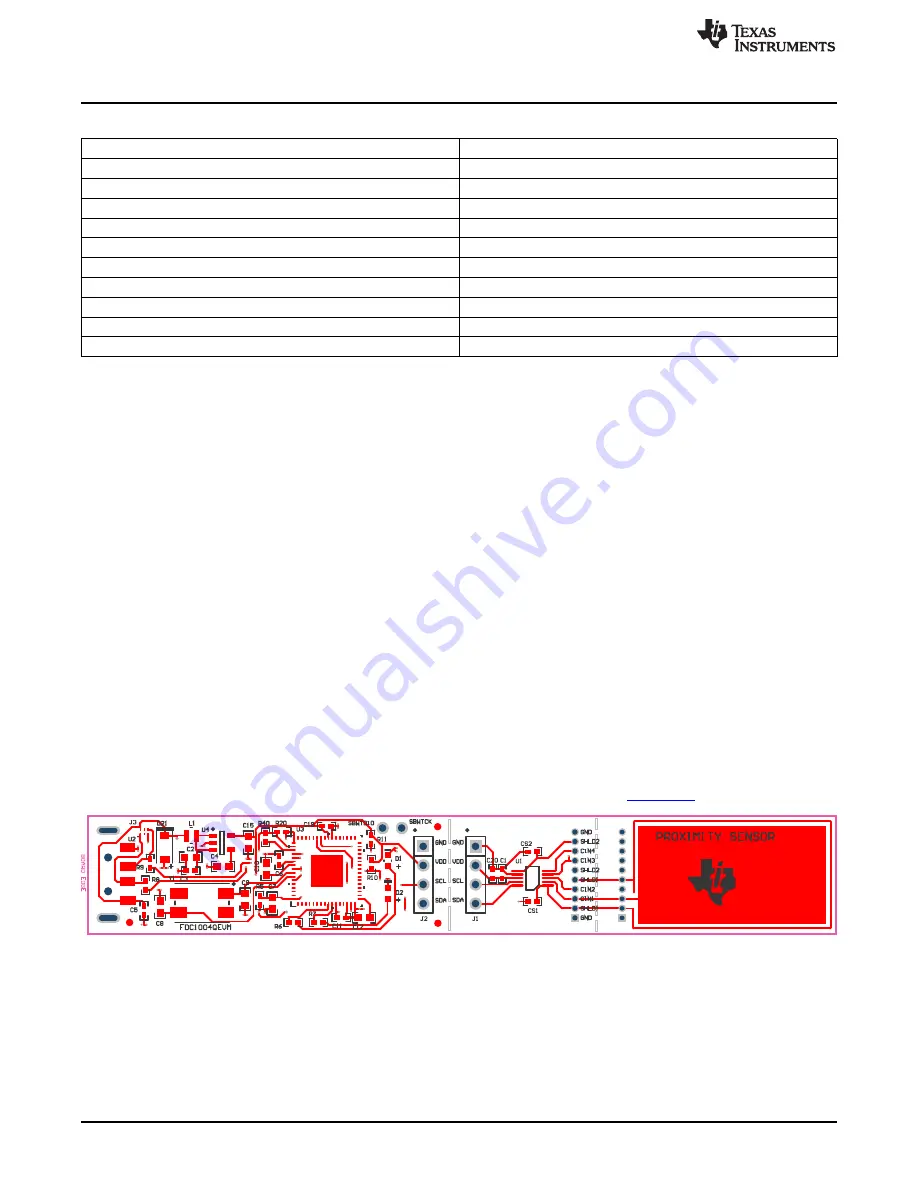
3
Board Layout
and
show the board layout of the FDC1004QEVM.
Sensor layout has been designed to demonstrate human proximity sensing with a single sensor. A shield
layer below the sensor and a shield ring around the sensor is designed to significantly reduce parasitic
capacitance interference from directions not intended to sense the target. The intended sensing area for
this EVM is towards the top side of the sensor. For more information about shielding, refer to the
application note
Capacitive Sensing: The Ins and Outs of Active Shielding
Figure 2. Top Layer Routing
6
FDC1004QEVM User's Guide
SNAU178 – April 2015
Copyright © 2015, Texas Instruments Incorporated