


Loading Example Code to the EVM
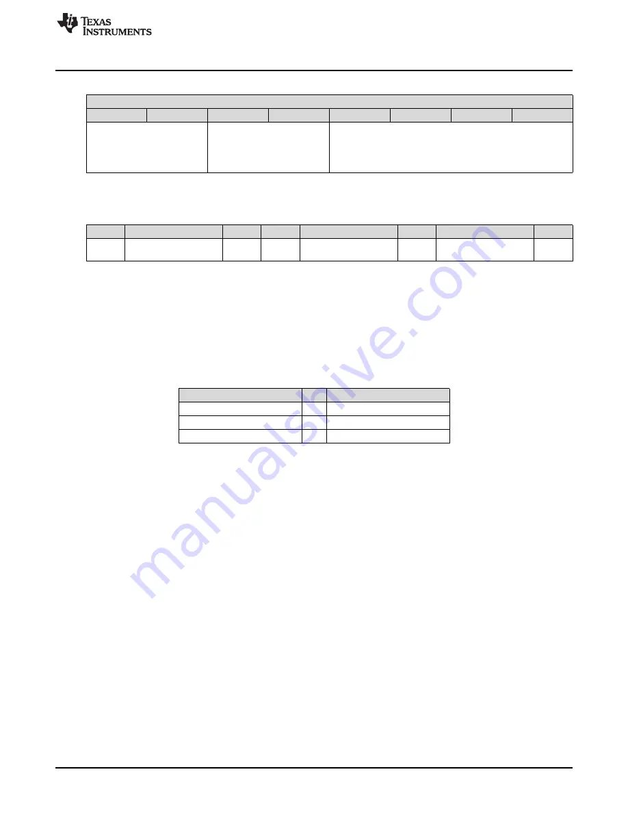
Table 14. Write Command
Write Data
Bit 7
Bit 6
Bit 5
Bit 4
Bit 3
Bit 2
Bit 1
Bit 0
Action
If Action = 01b or 10b, 0000b-1111b = Motor Speed
00b = Stop (also stops counter)
0000b = min speed (Stop, counter still updating)
Reserved (00b)
01b = Clockwise
1111b = max speed
10b = Counter Clockwise
No effect for Action = 00b or 11b
11b = Clear counter
•
Read command: Returns 2-byte counter value to the Master.
Table 15. Motor Board I
2
C Read Command
1 Bit
7 Bit
1 Bit
1 Bit
8 Bit
1 Bit
8 Bit
1 Bit
Counter Value
Counter Value
Start
Address: 0x02
1: Read
ACK
ACK
Stop
(Lower byte)
(Higher byte)
Two modes are switched automatically. If a button is pressed, the motor board switches to manual mode.
If the motor board receives a command form the I
2
C port, it switches to auto mode.
The firmware of the motor board can be customized. The firmware can be downloaded and debugged by
using the EZ-FET of the main board. The connection of the motor board and the main board is shown as
below. Be reminded that the C4 of the motor board may require to be removed for proper communication
of the spy-bi-wire connection.
Table 16. Connection for Downloading Firmware to the
Motor Board
Main Board
Motor Board
TEST_SBW (J102 Pin 1)
↔
(SBW Pin 1) TEST
RST_SBW (J102 Pin 3)
↔
(SBW Pin 2) RST
GND (J401 Pin 1)
↔
(EXT_PWR Pin 2) GND
5
Loading Example Code to the EVM
1. (Motor board) Insert batteries for the motor board.
2. (Motor board) Connect pin 1-2 of PWR_SEL using jumpers.
3. (Optional) Place the Main board and the Motor board on the fixture. (See Appendix)
4. (Main board) Attach the sensor board to the "ESI" of the main board.
5. (Main board) Connect pin 1-2 (TEST_SBW) and pin 3-4 (RST_SBW) of J102 using jumpers.
6. (Main board) Connect pin 1-2 (GND) and pin 3-4 (3V3) of J401 using jumpers.
7. (Main board) Connect the main board and the PC using an USB cable.
8. Switch on the motor board.
9. Launch Code Composer Studio™ IDE v6.0 on the computer.
10. Import example code project to the CCS workspace
11. Run Debug mode.
12. Place the motor board. Keep the position of the PCB wheel and the LC sensors approximately 5 mm
apart.
13. Click ‘Run’ to start the firmware on the main board.
15
SLAU611 – January 2015
EVM430-FR6989 Evaluation Kit
Copyright © 2015, Texas Instruments Incorporated