


GUI Operation
www.ti.com
10
SLVUB68 – October 2017
Submit Documentation Feedback
Copyright © 2017, Texas Instruments Incorporated
DRV8873x-Q1EVM User’s Guide
4
GUI Operation
The DRV8873x EVM GUI along with DRV8873x-Q1EVM facilitate control of brushed DC motors. The
DRV8873x EVM GUI provides functionality for adjusting the speed and direction of the motor, setting
various fault parameters such as voltage and current protection limits, observing the motor drive current,
and monitoring the device fault status. The GUI can also be used to test the motor for best performance
using various parameters available in the
Motor Control
page.
4.1
Hardware Setup
The hardware required to run the DRV8873x-Q1EVM is a micro-USB cable and a power supply from 4.5
to 38 V. Follow these steps to start up the DRV88873x-Q1EVM:
Step 1.
Connect the positive output of the DC power supply to the VM screw terminal and the
negative output to the GND screw terminal.
Step 2.
Use the OUT1 and OUT2 screw terminals to connect to the desired loads.
Step 3.
Connect a micro-USB cable to the DRV8873x-Q1EVM and computer.
Step 4.
Turn on the power supply and power up the printed circuit board (PCB).
4.2
Launching the DRV8873x EVM GUI
To launch the GUI, click on the DRV8873x EVM shortcut on the desktop or navigate to the Windows Start
Menu and click
All Programs
. Navigate to the Texas Instruments folder and select the DRV8873x EVM
icon.
For a guide on the different attributes of the DRV8873x EVM GUI, refer to the
DRV8873x EVM GUI User’s
Guide
.
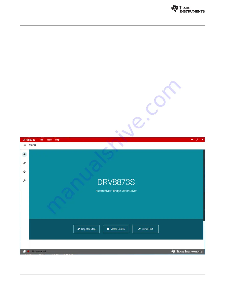
Figure 12
shows an example of the GUI.
Figure 12. Example of DRV8873x GUI Open