


Time
Base
A
c
c
e
l
R
a
te
Pulses Per Sec ond
DECAY = DAC_VALUE
·
2.5
V
¾
4095
Windows Application
20
SLVA344C – July 2009 – Revised July 2019
Copyright © 2009–2019, Texas Instruments Incorporated
Laser and Motor Drives
Figure 29. Current Control Frame
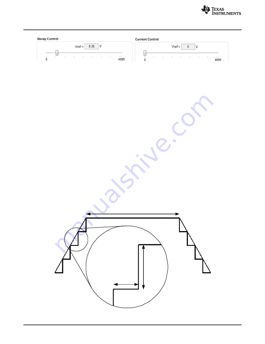
The MSP430F1612 12 bit DAC channel 1 is connected to the DRV8811 DECAY analog input. Changing
the DAC digital value from 0 to 4095, changes the analog voltage at the DECAY pin from 0 V to 2.5 V
respectively. See
(2)
Where DECAY is the output voltage and DAC_VALUE is a number from 0 to 4095.
3.5
Operating the Stepper Motor
3.5.1
Turning the Stepper Motor
The Windows Application, in conjunction with the MSP430F1612 microcontroller, utilizes a series of timers
to coordinate the rate of steps sent to the device. Once all the control signals are configured accordingly
(ENABLEn = LO, SLEEPn = HI, RESETn = HI; DIR, USM0 and USM1 can be HI or LO depending on
preferred mode of operation; SRn must be L, if external diodes are not populated), the motor is ready to
be turned.
The DRV8811EVM-001 customer EVM allows for the possibility of coordinating step rates such that
accelerating and decelerating profiles are achieved. Both acceleration and deceleration are controlled by
the same parameters, acceleration rate and time base.
When the motor starts, it always starts at the slowed pulses per second (PPS) speed (62 pulses per
second). The controller will accelerate the motor in order to reach the PPS speed. Acceleration rate is an
8-bit number (0 to 255) that gets added to the current PPS speed and time base is an 8-bit number (0 to
255) that specifies how many milliseconds will elapse from one speed increase to the next. Once the
specified PPS speed has been achieved, the acceleration stops.
Figure 30. Step Rate