Texas Instruments DRV8801EVM Скачать руководство пользователя страница 22

GUI Software Installation

www.ti.com

22

SLVU335A – February 2010 – Revised July 2019

Submit Documentation Feedback

Copyright © 2010–2019, Texas Instruments Incorporated
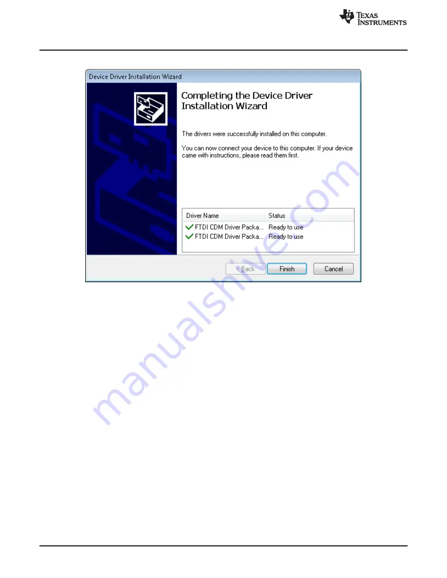
18. Click

Finish

to complete the Driver Installation.

Figure 17. Driver Installation Completion

Содержание DRV8801EVM

Страница 1: ...DRV8800 01 Evaluation Module User s Guide Literature Number SLVU335A February 2010 Revised July 2019...

Страница 2: ...ments Incorporated Table of Contents Contents 1 1 Introduction to EVM 5 1 1 Power Connectors 5 1 2 LEDs 5 1 3 Jumpers 5 1 4 Motor Outputs 6 1 5 System Requirements 6 2 GUI Software Installation 6 2 1...

Страница 3: ...3 9 Ready to Install 14 10 Downloading RTE 15 11 LabVIEW RTE Self Extraction 16 12 LabVIEW RTE Installation Initialization 17 13 Installation of LabVIEW RTE in Progress 18 14 FTDI Installation Initial...

Страница 4: ...www ti com 4 SLVU335A February 2010 Revised July 2019 Submit Documentation Feedback Copyright 2010 2019 Texas Instruments Incorporated List of Figures...

Страница 5: ...s easier by housing a microcontroller and an USB to Serial interface chip that allows for the user to control the different DRV8800 and DRV8801 signals by means of a graphical user interface GUI Figur...

Страница 6: ...ted OS Windows 7 32 Bit 64 Bit The window text size should be Smaller 100 Default Recommended RAM memory 4 GB or higher Recommended CPU Operating Speed 3 3 GHz or higher 2 GUI Software Installation Th...

Страница 7: ...19 Submit Documentation Feedback Copyright 2010 2019 Texas Instruments Incorporated 2 1 1 Installation Procedure The following procedure helps you install the DRV8800 01EVM GUI 1 Double click on the S...

Страница 8: ...bruary 2010 Revised July 2019 Submit Documentation Feedback Copyright 2010 2019 Texas Instruments Incorporated 2 The screen shown below in Figure 3 appears indicating installer initialization Click th...

Страница 9: ...entation Feedback Copyright 2010 2019 Texas Instruments Incorporated 3 In the newly open installation pop up window click Next The license agreement will be displayed Please read through it carefully...

Страница 10: ...opyright 2010 2019 Texas Instruments Incorporated 4 A screen as shown below in Figure 5 appears displaying the license agreement of National Instruments Please read through the agreement carefully and...

Страница 11: ...019 Submit Documentation Feedback Copyright 2010 2019 Texas Instruments Incorporated 5 Set the default directory for the GUI Installation and click Next Figure 6 Installation Directory Screen NOTE It...

Страница 12: ...10 2019 Texas Instruments Incorporated 6 A screen as shown in Figure 7 appears This screen is to select the components to install Select the Components to Install and Click Next to continue installati...

Страница 13: ...Copyright 2010 2019 Texas Instruments Incorporated 7 If LabVIEW RTE is selected as a component to install a screen appears as shown in Figure 8 Configure the proxy settings as required This screen is...

Страница 14: ...com 14 SLVU335A February 2010 Revised July 2019 Submit Documentation Feedback Copyright 2010 2019 Texas Instruments Incorporated 8 A screen as shown in Figure 9 appears Click Next to begin the instal...

Страница 15: ...2010 Revised July 2019 Submit Documentation Feedback Copyright 2010 2019 Texas Instruments Incorporated 9 If the LabVIEW RTE 2014 is selected as a component to install LabVIEW RTE downloads and perfo...

Страница 16: ...5A February 2010 Revised July 2019 Submit Documentation Feedback Copyright 2010 2019 Texas Instruments Incorporated 10 Once the Download completes LabVIEW begins with the self extraction as shown in F...

Страница 17: ...February 2010 Revised July 2019 Submit Documentation Feedback Copyright 2010 2019 Texas Instruments Incorporated 11 A screen appears as shown in Figure 12 It initializes the LabVIEW RTE Installation F...

Страница 18: ...ruary 2010 Revised July 2019 Submit Documentation Feedback Copyright 2010 2019 Texas Instruments Incorporated 12 A display as shown below appears which indicates the progress of LabVIEW RTE installati...

Страница 19: ...edback Copyright 2010 2019 Texas Instruments Incorporated 13 Once the LabVIEW RTE 2014 is installed DRV 8313 EVM GUI component installs 14 After DRV8800 01EVM Installation FTDI Installation begins A s...

Страница 20: ...i com 20 SLVU335A February 2010 Revised July 2019 Submit Documentation Feedback Copyright 2010 2019 Texas Instruments Incorporated 15 A screen as shown in Figure 15 appears click Next to proceed Figur...

Страница 21: ...umentation Feedback Copyright 2010 2019 Texas Instruments Incorporated 16 The License Agreement appears on screen as shown below 17 Read through the License Agreement carefully and enable the I Accept...

Страница 22: ...ww ti com 22 SLVU335A February 2010 Revised July 2019 Submit Documentation Feedback Copyright 2010 2019 Texas Instruments Incorporated 18 Click Finish to complete the Driver Installation Figure 17 Dri...

Страница 23: ...February 2010 Revised July 2019 Submit Documentation Feedback Copyright 2010 2019 Texas Instruments Incorporated 19 The Figure 18 screen appears denoting the completion of DRV8800 01EVM GUI Installat...

Страница 24: ...800 01EVM GUI requires the LabVIEW Run Time Engine 2014 to be installed before the GUI executes Please note the application is not compatible with other versions of LabVIEW Runtime Engine You can down...

Страница 25: ...ection which in turn selects the proper logic state for the DRV8800 01EVM control signals The Graphical User Interface GUI has been designed to allow for all of the DRV8800 01EVM device s functionalit...

Страница 26: ...GPIO Control Signals Once the application is communicating with the interface board the control signals can be actuated by checking or unchecking check boxes on the Signals frame Green in the Pin con...

Страница 27: ...01 EVM GUI Overview 27 SLVU335A February 2010 Revised July 2019 Submit Documentation Feedback Copyright 2010 2019 Texas Instruments Incorporated Figure 22 PHASE and ENABLE Pin Widgets Figure 23 PHASE...

Страница 28: ...ile menu contains the options as shown in Figure 24 Each of the options is explained below This is to Exit the application Figure 24 File Menu 3 2 2 View Under view there is an option Schematic which...

Страница 29: ...run in connected mode 3 2 3 2 Debug Log The Debug log option will enable to log all the activities of the user If that is not selected only the high level operations will be logged 3 2 3 3 Log to Fil...

Страница 30: ...DRV8800 01 EVM GUI Overview www ti com 30 SLVU335A February 2010 Revised July 2019 Submit Documentation Feedback Copyright 2010 2019 Texas Instruments Incorporated Figure 28 About Page...

Страница 31: ...ther than TI b the nonconformity resulted from User s design specifications or instructions for such EVMs or improper system design or c User has not paid on time Testing and other quality control tec...

Страница 32: ...These limits are designed to provide reasonable protection against harmful interference in a residential installation This equipment generates uses and can radiate radio frequency energy and if not in...

Страница 33: ...instructions set forth by Radio Law of Japan which includes but is not limited to the instructions below with respect to EVMs which for the avoidance of doubt are stated strictly for convenience and s...

Страница 34: ...any interfaces electronic and or mechanical between the EVM and any human body are designed with suitable isolation and means to safely limit accessible leakage currents to minimize the risk of electr...

Страница 35: ...R DAMAGES ARE CLAIMED THE EXISTENCE OF MORE THAN ONE CLAIM SHALL NOT ENLARGE OR EXTEND THIS LIMIT 9 Return Policy Except as otherwise provided TI does not offer any refunds returns or exchanges Furthe...

Страница 36: ...e resources are subject to change without notice TI grants you permission to use these resources only for development of an application that uses the TI products described in the resource Other reprod...

Отзывы: