5 Operating Modes
5.1 Stepper Motor
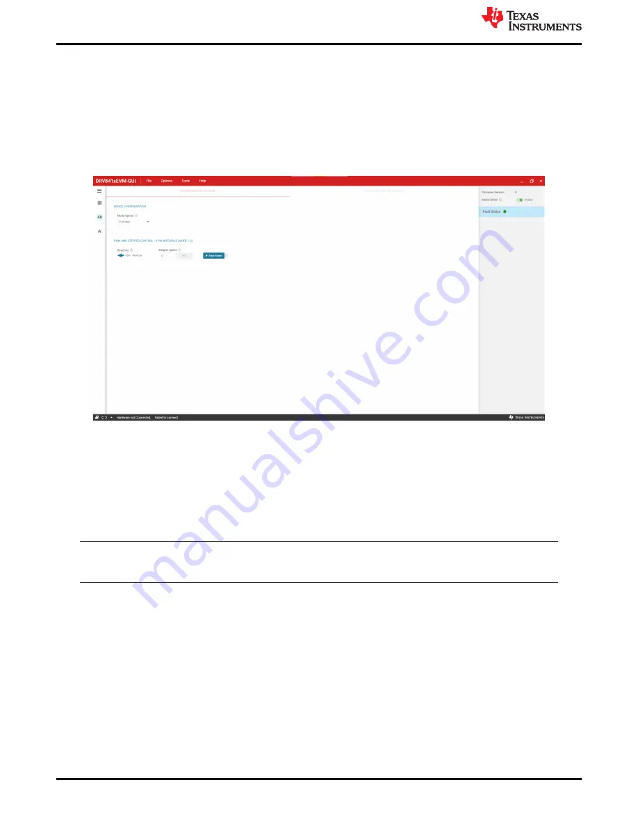
The DRV841x family of devices can drive a stepper motor or two brushed DC motors. Choosing the "Stepper
Motor Control" tab in the GUI displays the stepper control GUI page.
page. Hovering over the "!" icons display information about each widget. The "Mode Option" selects between full
step and half-step. Choosing half step will display another widget titled "Decay Mode" which sets th decay mode.
The "Direction" arrows sets the motor spin direction. The "Stepper Speed" sets the motor speed in pps (pulses
per second). Finally, the "Start Motor" button will spin the motor.
Figure 5-1. Stepper Motor Control Page
5.2 Brushed DC Motor
The brushed DC control page allows to configure between parallel h-bridge (AIN1-BIN1 duty cycle controlled by
AIN1 slider and AIN2-BIN2 controlled by AIN2 slider) and dual h-bridge (each control input signal controller by
an individual slider). The PWM switching frequency can be set between 20kHz, 10kHz, 5kHz, and 2.5kHz. The
user has the ability to use external custom PWM signals for AIN1, AIN2, BIN1, and BIN2 by connecting external
signal to the respective test points and removing the appropiate shunt on J9 header.
Note
In parallel h-bridge mode, ensure that J7 header is shorted to connect the SENSE resistor of both
h-bridges
Operating Modes
12
DRV8410_DRV8411_DRV8411AEVM User's Guide
SLEU121 – FEBRUARY 2022
Copyright © 2022 Texas Instruments Incorporated


