


Hardware Block Diagram
WARNING
This EVM is meant to be operated only in a lab environment, and TI
does not consider this EVM to be a finished end-product fit for
general consumer use. This EVM must be used only by qualified
engineers and technicians familiar with the risks associated with
handling high voltage electrical and mechanical components,
systems, and subsystems. This equipment operates at voltages
and currents that can result in electrical shock, fire hazard, and
personal injury, if not properly handled or applied. Equipment must
be used with necessary caution and appropriate safeguards
employed to avoid personal injury or property damage. The user
has the responsibility to confirm that the voltages and isolation
requirements are identified and understood prior to energizing the
board or simulation, or both. When energized, do not touch the
EVM or components connected to the EVM.
2
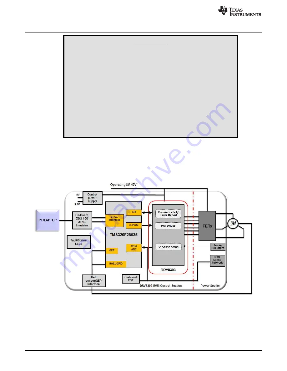
Hardware Block Diagram
illustrates a typical motor drive system running from a DC power supply. The DRV8303 motor
control board has all the power and control blocks that constitute a typical motor drive system for a PMSM
or BLDC motor.
Figure 2. DRV8303EVM Kit Hardware Block Diagram
3
Hardware Macro Blocks
The motor control board is separated into functional groups (referred to as macro blocks) that enable a
complete motor drive system. The following list describes the macro blocks present on the board and their
functions:
•
TMS320F28035 controller block with a built-in non-isolated XDS100 JTAG emulator
•
DC bus connection PVDD and GND terminals that connect to an external 8 to 60-V DC lab supply,
making sure to observe correct polarity
2
DRV8303EVM User Guide
SLVU983A – September 2013 – Revised October 2013
Copyright © 2013, Texas Instruments Incorporated