Texas Instruments DRV814x-Q1EVM Скачать руководство пользователя страница 20

resistors, and the OLP_CMP output status to update due to the latency between the EVM hardware and the 
GUI application.

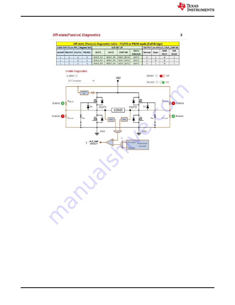
Figure 5-8. Passive Diagnostics Pop-Up Window

The Active Open Load Diagnostics are only for High-Side loads with the DRV824x device, Independent 
Half-Bridge mode, and the DRV814x Half-Bridge device. The Active Diagnostics not exist in the Hardware 
variants.

FAULTS

 Press the clear button to clear all the latched faults. Next to the clear button is the 

CONFIG

 button 

for SPI variants. This button allows the user to have more control over the modification of fault reporting. For 
example, selecting 

Automatic Retry

 would allow the faults to clear without any manual interference.

BRIDGE CURRENT

 The Bridge Current displays moving average and cycle peak load current values 

calculated from a window of samples of the voltage V

IPROPI

 (V

IPROPI

 = R

IPROPI

 × IPROPI) on the IPROPI 

output. Each periodic window of samples is referred to as a cycle. The samples are captured using the 
integrated 10-bit analog to digital converter in the MCU of the EVM. The displayed values are only indicative 
of the load current during the sampling window. The IPROPI analog output pin available on the header J4 
of the EVM can be used for accurate real-time measurement using a multimeter or for capturing the load 
current waveform using an oscilloscope. Current scaling is done by selecting a desired R

IPROPI

 resistor with 

the IPROPI jumper setting on the current limit headeer J2 of EVM. See 

Section 3.2.5

. Match the R

IPROPI 

setting on the GUI with the IPROPI jumper setting of the EVM.

Every control also has a help tip associated with it to quickly help the user while running the GUI.

5.3.3 Driver Control Page (HW Device Variant)

There are a few other minor differences between the SPI and HW device variant which are noted below:

WAKE

 For the Hardware variant, it is necessary for the jumpers to be selected while the device is asleep, 

and the default for the HW variant is "asleep". If the user makes changes to the jumpers while the device is 
awake, the device will not recognize those changes.

ENABLE DRIVER

 Directly controls the DRVOFF pin. When the bridge control is active the user cannot 

observe the passive diagnostics.

EVM GUI Operation

www.ti.com

20

DRV824x_DRV814x-Q1EVM User’s Guide

SLVUC46A – MARCH 2021 – REVISED JULY 2021

Submit Document Feedback

Copyright © 2021 Texas Instruments Incorporated

Содержание DRV814x-Q1EVM

Страница 1: ...Setup 14 5 2 Launching the DRV824x_DRV814x Q1EVM GUI Application 14 5 3 Using the DRV824x_DRV814x Q1EVM GUI Application 16 Trademarks All trademarks are the property of their respective owners 1 Revis...

Страница 2: ...eep mode is provided to achieve ultra low quiescent current draw by shutting down most of the internal circuitry The device offers voltage monitoring and load diagnostics as well as protection feature...

Страница 3: ...VM and DRV814x Q1EVM in the VQFN HotRod package The 28 pin leaded package HVSSOP or HTSSOP version of EVM leverages much of the same design and is also covered by this document From a firmware and GUI...

Страница 4: ...mware updates Main supply input A supply voltage ranging from 4 5 VDC to 36 VDC from a battery or a DC voltage source is connected to the large screw thermal block fused and reverse polarity protectio...

Страница 5: ...re 3 2 Typically resetting the MCU is not necessary however the MCU will automatically clear the nFAULT indicator on initial power up if you find the fault indicator is set due to cycling the power on...

Страница 6: ...out a computer or USB connection You can connect a brushed DC motor across OUT1 and OUT2 terminals of the DRV824x EVM or OUT and GND of the DRV814x EVM or simply an oscilloscope Note No diagnostics ar...

Страница 7: ...gure 3 4 illustrates the portions of the EVM associated with the main supply input powering the DRV824x Q1 or DRV814x Q1 device and the associated load s Starting from the upper left and working clock...

Страница 8: ...ting period Additionally BOM cost and PCB area is reduced by eliminating a large external power shunt resistor The off time PWM current regulation level can be configured during motor operation throug...

Страница 9: ...ediately adjacent to the silk screen label Note PH IN2 signal is not present on DRV814x Q1EVM variants Refer to your EVM schematic for more details Figure 3 6 DRV824x Q1EVM Signal and Control Header 3...

Страница 10: ...ly off It is also normal to briefly see this LED flash when the MCU becomes active or RESET is pressed This LED may flash continuously until VM power supply is turned on D3 VM VM supply indicator Norm...

Страница 11: ...et for more information regarding pin LVL settings and associated configuration Note IPROPI is common to both hardware and SPI EVM device variants and performs the same function Figure 3 8 DRV824x and...

Страница 12: ...r package corresponding to your operating system extract the archive and run the installer In Windows two new ports should be enumerated when the EVM is connected Figure 4 1 Figure 4 1 MSP430 EZFET_LI...

Страница 13: ...814x Q1EVM GUI 2 From the gallery click the icon in the latest version and select the installer for your operating system Windows Linux or Mac Refer back to Figure 4 3 in the previous section for a vi...

Страница 14: ...situations such as while disconnecting and reconnecting VM power before the power supply capacitors are fully discharged a proper firmware reset may not happen A proper reset is indicated by the STAT...

Страница 15: ...in Figure 5 2 Note If the EVM GUI does not register a successful connection after multiple attempts do a firmware update and then select an EVM variant for connecting using the GUI application Figure...

Страница 16: ...Variant The Register Map page shown below in Figure 5 4 allows the user to read write values to individual fields Register read back is read Every 1 sec by default Enabling this will start periodicall...

Страница 17: ...iagnostics MODE Programs the S_MODE register and will alter the appearance of the BRIDGE CONTROL depending on your selection There is a difference in MODE options between the DRV824x and DRV814x devic...

Страница 18: ...er This is especially important when in Independent Half Bridge mode The load connection warning will appear every time the user selects a new mode or repeatedly selects the current mode Figure 5 7 sh...

Страница 19: ...DRIVER is disabled Off state It will show up in a separate pop up window as can be seen in Figure 5 8 A representative table from the device datasheet is displayed in this window for guidance to perf...

Страница 20: ...of the load current during the sampling window The IPROPI analog output pin available on the header J4 of the EVM can be used for accurate real time measurement using a multimeter or for capturing th...

Страница 21: ...mage When operating the EVM at the maximum device specifications and higher ambient temperature external cooling fans may be required to minimize potential fire hazard personal injury or both 5 3 4 Up...

Страница 22: ...are subject to change without notice TI grants you permission to use these resources only for development of an application that uses the TI products described in the resource Other reproduction and...

Отзывы: