www.ti.com
Reference
8.2
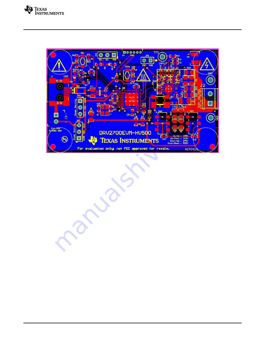
PCB Layout
Figure 19
shows the DRV2700EVM-HV500 PCB layout.
Figure 19. Top and Bottom Layers
21
SLOU407A – April 2015 – Revised May 2015
DRV2700EVM-HV500 High Voltage Piezo Driver Evaluation Kit
Submit Documentation Feedback
Copyright © 2015, Texas Instruments Incorporated


