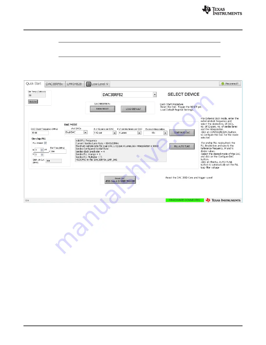
Quick Start
10
SLAU671A – October 2016 – Revised March 2017
Copyright © 2016–2017, Texas Instruments Incorporated
DAC38RF8xEVM
lanes) and interpolation (16x), as shown in
NOTE:
It is important to record the calculated value of ‘SMA J4 CLK’ and set the frequency of
the signal generator connected to SMA J4 to this frequency.
6. Note the messages displayed for information about the SerDes rate, maximum allowed sample rate for
the selected mode, and which HSDC Pro ini file to select (see the section on
for more
information). If the DAC clock frequency is not supported for the selected mode, the
DAC Clock
Frequency
box blinks.
Figure 8. DAC38RF8xEVM GUI Quick Start Page Configured for On-Chip PLL Mode
7. Click on
CONFIGURE DAC
button to load the DAC configuration data.
8. Click on the
PLL AUTO TUNE
button to automatically search for the correct PLL loop filter voltage
setting. If desired, the PLL may be manually tuned by stepping through the VCO tune control until the
PLL LF voltage is either 3 or 4. Both the VCO tune control and PLL LF voltage indicator are available
on the DAC38RF8x
→
Clocking tab.
9. Click on
Reset DAC JESD Core & SYSREF TRIGGER
button.
2.1.6
High Speed Data Converter Pro (HSDC Pro)
1. Open High Speed Data Converter Pro by going to
Start Menu
→
All Programs
→
Texas Instruments
→
High Speed Data Converter Pro
.
2. Select the
DAC
tab.
3. Use the
Select DAC
drop-down menu at the top left corner and select the appropriate .ini file (for this
example, the ini file is DAC38RF8x_LMF_841). Check the DAC38RF8x GUI message box on the quick
start page for the appropriate .ini file to use based on the DAC mode selected.
4. When prompted to update the firmware for the DAC, click “Yes” and wait for the firmware to download
to the TSW14J56.


