1
24
8
9
D23
D16
D15
D0
Read command
SYNC
SCLK
SDI
SDO
1
24
8
9
D23
D16
D15
D0
Any command
D23
D16
D15
D0
Read Data
HiZ
HiZ
HiZ
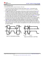
Figure 7-15. SPI Read Cycle
The daisy-chain operation is also enabled with the SDO pin.
shows that in daisy-chain mode,
multiple devices are connected in a
chain
with the SDO pin of one device is connected to SDI pin of the following
device. The SPI host drives the SDI pin of the first device in the chain. The SDO pin of the last device in
the chain is connected to the POCI pin of the SPI host. In four-wire SPI mode, if the access cycle contains
multiples of 24 clock edges, only the last 24 bits are used by the device first device in the chain. If the access
cycle contains clock edges that are not in multiples of 24, the SPI packet is ignored by the device.
describes the packet format for the daisy-chain write cycle.
SDI
SDO
SCLK
SYNC
TI SPI Device
TI SPI Device
TI SPI Device
C
B
A
SDI
SDO
SCLK
SYNC
SDI
SDO
SCLK
SYNC
R
PULL-UP
VIO
R
PULL-UP
VIO
R
PULL-UP
VIO
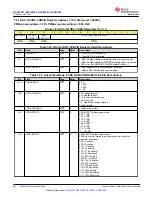
Figure 7-16. SPI Daisy-Chain Connection
1
24
8
9
D23
D16
D15
D0
Device A command
SYNC
SCLK
SDI-C
SDO-C
D23 – D1
Device B command
D0
25
48
D23 – D1
Device C command
D0
49
72
Device A command
Device B command
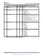
Figure 7-17. SPI Daisy-Chain Write Cycle
DAC53001, DAC53002, DAC63001, DAC63002
SLASF48 – MAY 2022
Copyright © 2022 Texas Instruments Incorporated
47
Product Folder Links:


