www.ti.com
Schematics and Layout
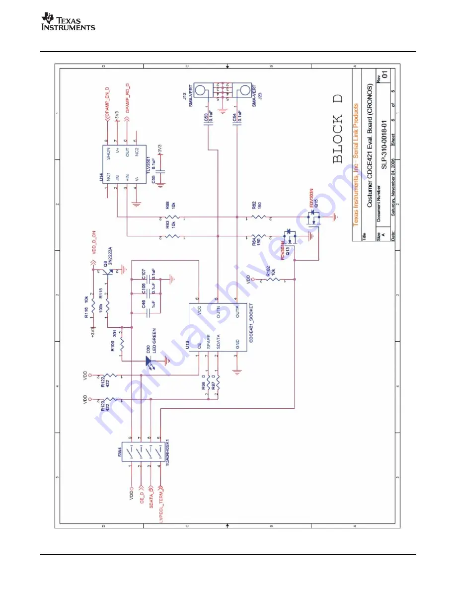
Figure 14. CDCE421EVM Board—Block D Schematic
SCAU020 – March 2007
10.9MHz–1175MHz Low Phase Noise Clock Evaluation Board
19
Submit Documentation Feedback
Страница 1: ...10 9MHz 1175MHz Low Phase Noise Clock Evaluation Board User s Guide March 2007 Serial Link Products SCAU020...
Страница 2: ...2 SCAU020 March 2007 Submit Documentation Feedback...
Страница 3: ...nabled Automatic PLL Selection 9 6 2 Manual PLL Block Selection Advanced Control 11 7 Configuring the Board 13 7 1 Programming and Testing Configuration USB Cable Attached Default Configuration 13 7 2...
Страница 4: ...op Up 10 7 Chronos GUI Manual PLL Block Selection Pop Up 11 8 JP1 Setting for USB Programming Configuration 13 9 CDCE421EVM Block Switch Off 14 10 CDCE421EVM Board Schematic 15 11 CDCE421EVM Board Blo...
Страница 5: ...try that operates in conjunction with an external AT cut crystal to produce a stable frequency reference for the PLL based frequency synthesizer A 3 3V LVCMOS level input can also be used instead of a...
Страница 6: ...the respective switches in the same manner The CDCE421 output frequency is always an integer multiple or integer divide of the input frequency and is determined through selection of VCO1 or VCO2 and t...
Страница 7: ...rth block D includes a socket fitting the oscillator part used in Block C The provided EVM software is controlled through a graphical user interface GUI The software allows users to easily send comman...
Страница 8: ...Setup msi file available on the CD shipped with the EVM Figure 3 appears Be sure to note the installation folder the USB driver must be installed in the same after setup completes and the USB cable is...
Страница 9: ...tware GUI The software illustration Figure 5 shows the on chip PLL structure of the CDCE421 Through this screen the user can change the Input Frequency PFD Charge Pump Loop Filter and Output Type The...
Страница 10: ...reference input to the CDCE421 for example from an oscillator or crystal the maximum bandwidth and phase margin setting must be used 400kHz bandwidth and 80 degrees The Phase Frequency Detector PFD ch...
Страница 11: ...al blocks within the PLL If a user is familiar with PLL operation one may activate individual control of the PLL blocks by clicking on the Advanced Control button activating the window shown in Figure...
Страница 12: ...ould be kept at 0000 ibias_100ua Other settings are for TI use only Chronos IC Config Select Use U13 programming socket for rapid programming of Chronos enabled devices Select Use U8 DIE U9 QFN socket...
Страница 13: ...vised to enable this setup for saving configuration settings to the CDCE421 and later powering the device from its internal memory This option is useful if there is not a USB port available in a lab o...
Страница 14: ...14 show the printed circuit board PCB schematics Note Board layouts are not to scale These figures are intended to show how the board is laid out they are not intended to be used for manufacturing CDC...
Страница 15: ...www ti com Schematics and Layout Figure 10 CDCE421EVM Board Schematic SCAU020 March 2007 10 9MHz 1175MHz Low Phase Noise Clock Evaluation Board 15 Submit Documentation Feedback...
Страница 16: ...www ti com Schematics and Layout Figure 11 CDCE421EVM Board Block A Schematic 16 10 9MHz 1175MHz Low Phase Noise Clock Evaluation Board SCAU020 March 2007 Submit Documentation Feedback...
Страница 17: ...www ti com Schematics and Layout Figure 12 CDCE421EVM Board Block B Schematic SCAU020 March 2007 10 9MHz 1175MHz Low Phase Noise Clock Evaluation Board 17 Submit Documentation Feedback...
Страница 18: ...www ti com Schematics and Layout Figure 13 CDCE421EVM Board Block C Schematic 18 10 9MHz 1175MHz Low Phase Noise Clock Evaluation Board SCAU020 March 2007 Submit Documentation Feedback...
Страница 19: ...www ti com Schematics and Layout Figure 14 CDCE421EVM Board Block D Schematic SCAU020 March 2007 10 9MHz 1175MHz Low Phase Noise Clock Evaluation Board 19 Submit Documentation Feedback...
Страница 20: ...oduct This notice contains important safety information about temperatures and voltages For additional information on TI s environmental and or safety programs please contact the TI application engine...
Страница 21: ...iness practice TI is not responsible or liable for any such statements TI products are not authorized for use in safety critical applications such as life support where a failure of the TI product wou...