


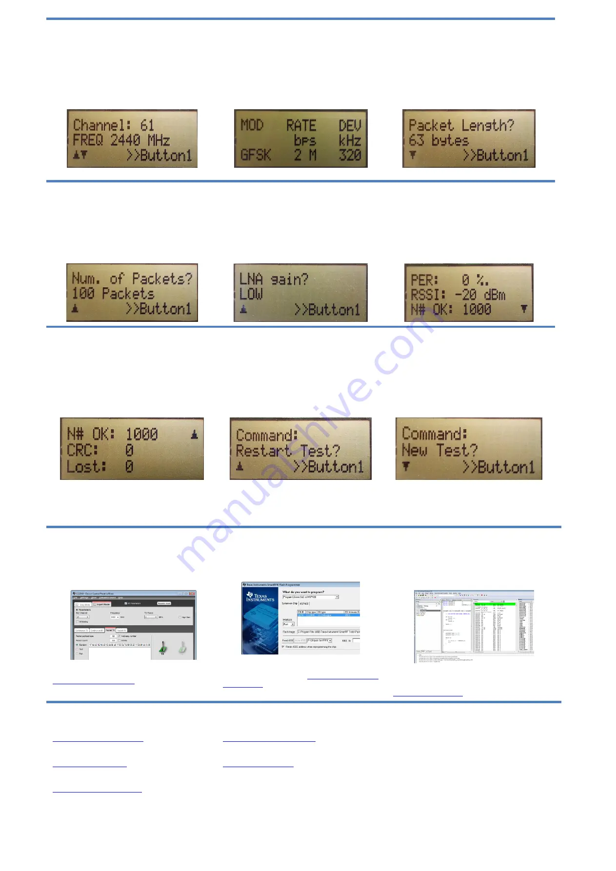
10. Frequency Selection
When the Remote mode is chosen, a series of
settings must be configured to set up the link for
the PER test. The frequency must be selected
first (the selectable frequency range is from 2402
MHz to 2480 MHz). Move the joystick up or down
to change the frequency (channel) and press S1
to confirm the choice.
11. Modulation Setup
There are 7 different modulation schemes
available. The different bitrates are 250 Kbps,
500 Kbps, 1Mbps and 2 Mbps. MSK modulation
is available for 250 Kbps and 500 Kbps data rate
while GFSK has all of the mentioned above.
Move the joystick up or down to change the
scheme and press S1 to confirm the choice.
12. Packet Length
The packet length can be set to 10, 16, 32 or 63
bytes. Move the joystick up or down to change
the packet length and press S1 to confirm the
choice.
13. Number of Packets
The total number of packets to be sent for each
run can be set to 100, 1000, 10000, 100000 and
1000000. Move the joystick up or down to
change the number of packets and press S1 to
confirm the choice.
14. LNA Gain
For the 2Mbps data rates the AGC is enabled,
while for lower rates the LNA gain must be set to
HIGH or LOW. Move the joystick up or down to
change between LOW and HIGH gain and press
S1 to confirm the choice. After confirming the last
choice the configuration packet will be sent to the
Master device and the PER test begins.
15. Results I
The packet error rate (PER) is presented as the
sum of lost packets and packets with CRC error
per thousand. The received signal strength
indication (RSSI) is presented as a running
average of the eight last samples. The number of
received packets is continuously updated on the
LCD display while the test is running.
13. Results II
When the test is complete a small downward
facing arrow will show in the bottom right of the
LCD screen. This indicates that the test is
complete and that there is an additional results
screen “below”. Move the joystick up and down
to jump between the two test result screens.
Press the S1 button to exit the test results.
14. Repeat Test
After exiting the test results the user is presented
with two choices.
If “Restart Test” is chosen the
same test as previously run will be repeated. The
test can also be restarted at any time during the
test by pushing the S1 button. Move the joystick
up or down to switch between the two commands
and press S1 to confirm the choice.
15. New Test
If “New Test” is chosen the application will return
to setting up the configuration for a new test,
starting at frequency selection. The test can also
be stopped at any time during the test by pushing
on the joystick like a button.
Additional Tools and Links
SmartRF
™ Studio
SmartRF Studio allows you to configure the radio,
run RF performance tests, and run link tests
between the two SmartRF05EBs.
SmartRF Studio can be downloaded from
SmartRF Flash Programmer
Texas Instruments has a simple tool which can
be used to program and flash the CC2545.
SmartRF
Flash
Programmer
can
be
downloaded
from
IAR Embedded Workbench
To develop software, program, and debug the
CC2545, you should use IAR Embedded
Workbench for 8051.
More information on IAR EW8051, including a
free evaluation version download, can be found at
Useful Links
CC2545EMK Product Page:
CC2543/44/45 Development Kit
User’s Guide:
CC2545 Product Page:
www.ti.com/product/cc2545
Useful Links
CC254x
User’s Guide:
For additional help, visit the TI E2E Forums: