


CC253x
CC2541
V
CC
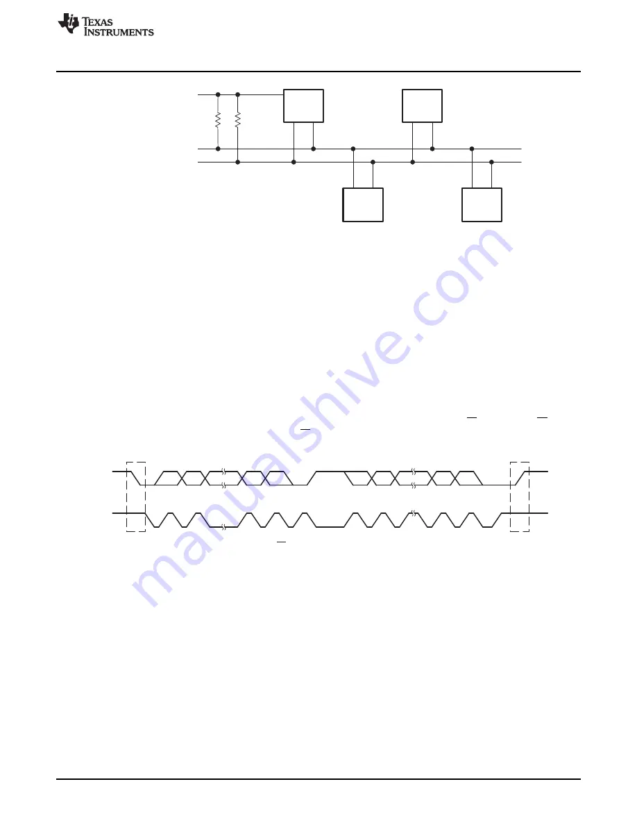
Serial Data (SDA)
Serial Clock (SCL)
Device A
Device B
Device C
SDA
SCL
MSB
Acknowledgement
Signal From Receiver
Acknowledgement
Signal From Receiver
1
2
7
8
9
1
2
8
9
ACK
ACK
START
Condition (S)
STOP
Condition (P)
R/W
Operation
Figure 20-2. I
2
C Bus Connection Diagram
20.1.1 I
2
C Initialization and Reset
The I
2
C module is enabled by setting the
I2CCFG.ENS1
bit. It is then in the not-addressed slave state.
The I
2
C configuration and state is not retained in power modes PM2 and PM3. It must be reconfigured
after coming out of sleep mode.
The I
2
C module is not reset when disabled, and retains its internal state until the next time
I2CCFG.ENS1
is set.
20.1.2 I
2
C Serial Data
One clock pulse is generated by the master device for each data bit transferred. The I
2
C module operates
with byte data. Data is transferred MSB first as shown in
.
The first byte after a START condition consists of a 7-bit slave address and the R/W bit. When R/W = 0,
the master transmits data to a slave. When R/W = 1, the master receives data from a slave. The ACK bit
is sent from the receiver after each byte on the ninth SCL clock.
Figure 20-3. I
2
C Module Data Transfer
START and STOP conditions are generated by the master and are shown in
. A START
condition is a high-to-low transition on the SDA line while SCL is high. A STOP condition is a low-to-high
transition on the SDA line while SCL is high.
Data on SDA must be stable during the high period of SCL (see
). The state of SDA can only
change when SCL is low, otherwise a START or STOP condition is generated.
179
SWRU191C
–
April 2009
–
Revised January 2012
I
2
C
Copyright
©
2009
–
2012, Texas Instruments Incorporated


