Texas Instruments BUF12800 Скачать руководство пользователя страница 19

V

=

DAC_CHANNEL

15 V x 68

1024

= 0.996 V

www.ti.com

BUF12800EVM Software Overview

19

SBOU116A – September 2011 – Revised August 2016

Submit Documentation Feedback

Copyright © 2011–2016, Texas Instruments Incorporated

BUF12800EVM Evaluation Board and Software Tutorial

For example:

Channel 6: Code 44 (hexadecimal) = 68 (decimal)

(4)

6.2.3

Read DAC Button

By pressing the

Read DAC

button in the BUF12800EVM software, all of the BUF12800 DAC registers are

read to obtain the respective current register contents. Once the read procedure is complete, all of the
corresponding text boxes are updated to show the current values present in the DAC registers.

6.2.4

Write DAC Button

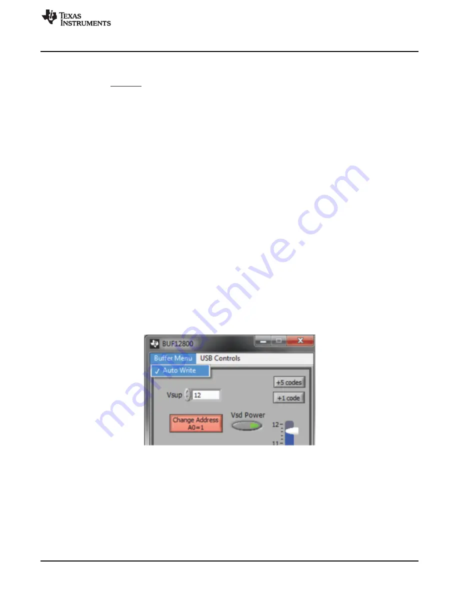
The method used to write the values in the DAC registers is based on whether or not the Auto Write
feature is enabled. The BUF12800 has two methods of writing information into the DAC registers. The first
method allows for the output voltage to change immediately after the writing to the DAC register. In the
BUF12800EVM software, this mode is configured by enabling the Auto Write feature found in the

Buffer

Menu

drop-down menu. In this mode, as an individual channel is written to, the output voltage changes as

soon as the user moves to a different text box in the software.

The second method of writing to the DAC registers allows for the user to write multiple channels and then
have all of the output voltages change at the same time, rather than each channel voltage changing as
soon as it is written to. Disabling the Auto Write feature in the software allows the user to enter all of the
desired values for all of the channels, and then press the

Write DAC

button to change all of the output

voltage of all of the channels at one time. When the Auto Write feature is enabled, no change occurs to
the output voltages when the

Write DAC

button is pressed. This action occurs because after the text box

for a given channel has been updated, as soon as another item in the software is clicked, the Auto Write
feature automatically performs a write command to the updated channel that then updates the output
voltage. When in the Auto Write enabled mode, the Write DAC button cannot be pressed with data in the
corresponding channel text boxes that are different than the values already stored in the DAC register; no
change to the DAC registers will occur.

Figure 18

shows the location in the Buffer Menu with the Auto

Write feature enabled. Click the Auto Write feature again to enable/disable the feature, depending upon its
current state.

Figure 18. Auto Write Feature Enabled

6.2.5

Reset Button

Pressing the

Reset

button in the BUF12800EVM software performs two functions. First, a General-Call

Reset for the BUF12800 is performed. The status of the DAC registers after this General-Call Reset
default to

1000000000

, or mid-supply. The second function performed after the

Reset

button is pressed is

that a Read DAC call is made to update the corresponding channel text boxes to the current value for
each channel.

Содержание BUF12800

Страница 1: ...hematic printed circuit board PCB layout drawings and a parts list for the EVM Contents 1 Overview 2 2 BUF12800EVM Hardware Setup 3 3 BUF12800EVM Hardware 5 4 BUF12800EVM Features 11 5 BUF12800EVM Sof...

Страница 2: ...you also check the BUF12800 product folder on the TI web site at www ti com to verify that you have the latest versions of the related software Table 1 BUF12800EVM Kit Contents Item Quantity BUF12800...

Страница 3: ...l 2 BUF12800EVM Hardware Setup This section discusses the overall system setup for the BUF12800EVM The PC runs software that communicates with the USB_DIG_Platform The USB DIG Platform generates the a...

Страница 4: ...ard Block Diagram 2 2 Signal Definitions of J1 25 Pin Male DSUB Table 3 shows the various signals connected to J1 on the BUF12800 test board 1 When power is switched off digital I O is also switched o...

Страница 5: ...neral purpose data acquisition system that is used on several different Texas Instruments evaluation modules The details of its operation are included in a separate document SBOU058 available for down...

Страница 6: ...n applying power The external connections may be connected to the real world system that the BUF12800 is to be incorporated into Figure 4 shows the typical hardware connections Figure 4 Typical Hardwa...

Страница 7: ...Note that it is always necessary to connect the power to the DIG before connecting the USB cable If the USB cable is connected before the power the computer may attempt communication to an unpowered...

Страница 8: ...cable Typically the computer responds with a Found New Hardware USB Device pop up dialog The popup window typically changes to Found New Hardware USB Human Interface Device This pop up window indicate...

Страница 9: ...al 3 6 BUF12800EVM Default Jumper Settings Figure 8 shows the default jumpers configuration for the BUF12800EVM In general the jumper settings of the USB DIG Platform do not need to be changed You may...

Страница 10: ...The default INT position connects the SDA pin to the I2C_SDA_ISO control signal JMP4 INT This jumper selects whether the LD pin on the BUF12800 is connected to jumper JMP5 or whether the LD pin is co...

Страница 11: ...t supply VDUT 5 V or 3 V This jumper is typically the only jumper that changes for most applications JUMP10 WP ON This write protects the firmware EEPROM JUMP11 WP ON This write protects the calibrati...

Страница 12: ...5 is used to select the reference voltage that is connected to the LD latch pin It is used only when jumper JMP4 is set to INT If JMP5 is set to H the latch pin is connected to the VSD supply voltage...

Страница 13: ...n while the device is placed in this socket it cannot be operated to its full output capability as a result of thermal dissipation limitations CAUTION Only one location should be populated at a time T...

Страница 14: ...art the installation The BUF12800 software installer file then opens to begin the installation process as shown in Figure 9 Figure 9 BUF12800EVM Software Install Window After the installation process...

Страница 15: ...ustrates Once the installation process is completed click Finish Figure 11 BUF12800EVM Software Installation Progress 5 3 Software Description and Set Up The BUF12800EVM software allows the user to re...

Страница 16: ...00EVM Software Overview This section discusses how to use the BUF12800EVM software 6 1 Starting the BUF12800EVM Software The BUF12800EVM software can be operated through the Start menu in Windows From...

Страница 17: ...problem with the USB Human Interface Device Driver on the computer you are using Make sure that the device is recognized when the USB cable is plugged in this action is indicated by a Windows generat...

Страница 18: ...e 16 JMP6 Setting for Logic 1 6 2 2 Measuring the Power Supply You must measure the power supply VS with respect to the GND on the BUF12800 Test Board and enter it in the Vsup field located in the top...

Страница 19: ...e same time rather than each channel voltage changing as soon as it is written to Disabling the Auto Write feature in the software allows the user to enter all of the desired values for all of the cha...

Страница 20: ...hexadecimal refer to Figure 13 The DAC codes that is gamma voltages can also be saved to a text file txt using the Save to File button Pressing the Save to File button opens a file save dialog box sim...

Страница 21: ...ext file that can be opened in a text editor as illustrated in Figure 20 Figure 20 Saved Data Format 6 2 7 Load From File Button The BUF12800EVM software is also able to load data saved from previous...

Страница 22: ...selected Adjusting the slider bar then only updates the highlighted channel The final method to change the DAC voltages is through the 1 Code and 5 Code buttons on the main software window These butt...

Страница 23: ...the Control Panel button brings up a display panel that allows you to adjust each channel using a set of graphical sliders as shown in Figure 23 Simply drag the slider to adjust the desired channel ou...

Страница 24: ...al 7 BUF12800EVM Documentation This section contains the complete bill of materials and PCB layout for the BUF12800EVM NOTE These board layouts are not to scale These image are intended to show how th...

Страница 25: ...ised August 2016 Submit Documentation Feedback Copyright 2011 2016 Texas Instruments Incorporated BUF12800EVM Evaluation Board and Software Tutorial 7 2 PCB Layout Figure 25 shows the PCB layout of th...

Страница 26: ...onnector D SUB Plug R A 25 Pos 30 Gold with threaded inserts and board locks AMP Tyco Electronics 5747842 4 8 4 T1 to T4 Terminal block 5 MM 2 Pos On Shore Technology Inc ED300 2 9 1 T5 Terminal block...

Страница 27: ...ing the warranty period to the address designated by TI and that are determined by TI not to conform to such warranty If TI elects to repair or replace such EVM TI shall have a reasonable time to repa...

Страница 28: ...transmitter has been approved by Industry Canada to operate with the antenna types listed in the user guide with the maximum permissible gain and required antenna impedance for each antenna type indic...

Страница 29: ...ified allowable ranges some circuit components may have elevated case temperatures These components include but are not limited to linear regulators switching transistors pass transistors current sens...

Страница 30: ...REMOVAL OR REINSTALLATION ANCILLARY COSTS TO THE PROCUREMENT OF SUBSTITUTE GOODS OR SERVICES RETESTING OUTSIDE COMPUTER TIME LABOR COSTS LOSS OF GOODWILL LOSS OF PROFITS LOSS OF SAVINGS LOSS OF USE L...

Страница 31: ...sponsible for compliance with all legal regulatory and safety related requirements concerning its products and any use of TI components in its applications notwithstanding any applications related inf...

Отзывы: