Texas Instruments bq76PL536A Скачать руководство пользователя страница 16

PLOTTING

www.ti.com

7.3

Plotter Controls

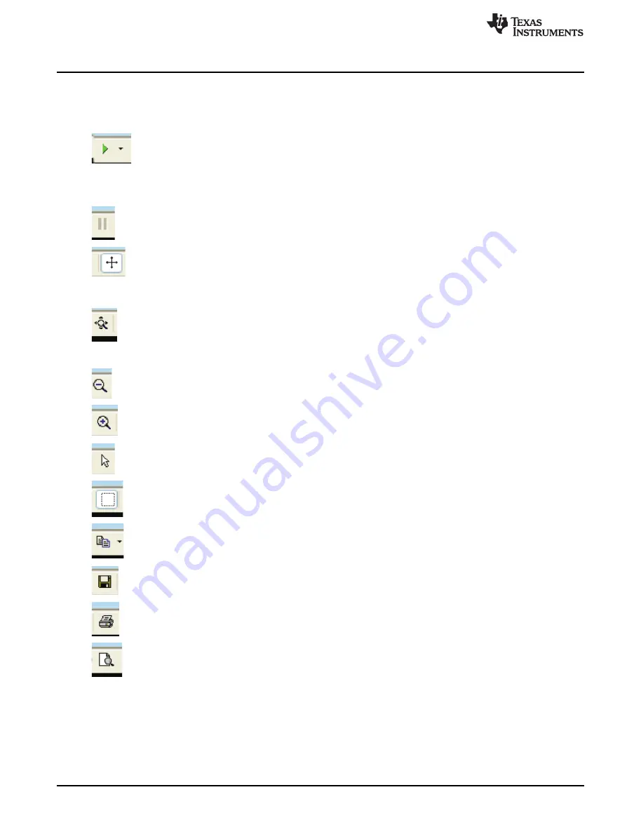
Plotter controls are shown slightly magnified in the upper left of the capture above. From the left, they
control:

RESUME TRACKING

- causes the strip-chart to resume automatically tracking

changes in voltage, time, or temperature – in other words, resume auto-ranging. This
green arrow is illuminated after manually zooming in or opening a window in the
default view. The default is auto-ranging is enabled. The small black down-arrow
opens a small menu of selections controlling the automatic tracking. Whether
displayed or not, data are always captured on each poll refresh.

PAUSE DISPLAY

– momentarily stops auto-tracking. To resume, use the RESUME

TRACKING button described above.

SCROLL X-Y

– After clicking this control, the display (data) window can be moved by

left-clicking the mouse button in the display and moving the mouse. Use RESUME
TRACKING to restore the display. Each data set (VCn voltages, VBRICK, temperature,
time) scale can be individually moved by clicking and holding the left mouse button on
the units field and scrolling up-down or left-right (time scale).

EXPAND X-Y

– This control allows zooming in or out on the displayed scale. Choose

this button, then click and hold the left mouse button to operate. Each data set (VCn
voltages, VBRICK, temperature, time) scale can be individually zoomed by clicking and
holding the left mouse button on the units field and scrolling up-down or left-right (time
scale).

ZOOM OUT

– click on a scale, then click this button to move out in incremental steps.

ZOOM IN

– similar but opposite action to Zoom out, above.

SELECT

– allows selecting data or scales (opposite of window mode, described next)

WINDOW

– click this button, then drag a zoom box around an area in the display to

zoom in. This mode is canceled by clicking on the SELECT arrow described above.
The display is restored by using the TRACKING RESUME button, above.

COPY TO CLIPBOARD

– the data are copied to the clipboard for inclusion in a

document or spreadsheet. A small menu allows selecting the numeric data to copy, or
the graphic.

SAVE

– the graphic to a .PNG file

PRINT

– the graphic to a printer

PRINT PREVIEW

– see what the graphic will look like on your printer before printing.

16

bq76PL536A and bq76PL536A-Q1 EVM Quick Start Guide

SLUU437D – October 2010 – Revised July 2015

Submit Documentation Feedback

Copyright © 2010–2015, Texas Instruments Incorporated

All manuals and user guides at all-guides.com

Содержание bq76PL536A

Страница 1: ...ng the adapter for the first time The Aardvark driver should be installed prior to installing the TI supplied bq76PL536A and bq76PL536A Q1 Evaluation software 1 Download the USB Drivers Windows from t...

Страница 2: ...ed to use the EVM with power supplies in place of cells see Use with 12 26 VDC Power Supply Connect cells to the supplied mating connectors with screw terminals BEFORE plugging the connector into the...

Страница 3: ...he pin that will connect to the bottom most pin of the mating connector The positive connection is made to pin 7 the top most on the connector It is not necessary to connect to the intermediate pins d...

Страница 4: ...ust remain isolated from earth ground EVM Assembly and Configuration www ti com Figure 1 Correct Connection of Three 20 V Power Supplies to bq76PL536EVM 3 Figure 2 Alternate Connection for a Single 54...

Страница 5: ...sufficient current to ICs Base IC must be powered www ti com EVM Assembly and Configuration Figure 3 Incorrect Connections Base IC Not Powered Figure 4 Incorrect Connections Insufficient VBAT Per IC 5...

Страница 6: ...rder from negative to positive in lieu of powering all three devices Due to poor termination of the unpowered devices in this configuration detailed testing or critical hardware evaluations should not...

Страница 7: ...ack where lethal voltages may be present The galvanic isolation provided by the ISO COMMS section does not eliminate the need for safe handling procedures proper High Voltage equipment and protective...

Страница 8: ...ICK The voltage measured by the bq76PL536A between the BATx and VSS pins VCELLn The voltage measured between the pair of pins VCn VCn 1 that is VCELL2 VC2 VC1 ADDR Displays the address of the device b...

Страница 9: ...operation in circuit Some Group 3 registers are shown as registers at the bottom of the left side of the screen the others in the top right section of the screen as listboxes and registers 5 1 3 Quick...

Страница 10: ...This list box allows choosing a polling rate between 100ms and 60s The LED illuminates green each time the GUI polls the device stack Useful as a heartbeat indicator when polling or logging is active...

Страница 11: ...update The user hould see all cell voltages displayed along with registers showing FAULT and ALERT status DEVICE STATUS etc 5 3 Menus and Commands 5 3 1 File Menu This menu provides a way to save comp...

Страница 12: ...RTS at startup Programmers wishing to check their code will want to disable most of these startup niceties during final code checkout See Packing List for details of the startup Options MEASUREMENT FI...

Страница 13: ...itor Showing Communications Error 13 SLUU437D October 2010 Revised July 2015 bq76PL536A and bq76PL536A Q1 EVM Quick Start Guide Submit Documentation Feedback Copyright 2010 2015 Texas Instruments Inco...

Страница 14: ...DISABLE CUV sets the CONFIG_CUV DISABLE bit disabling CUV ALERTs CLEAR LATCHED BITS clears all FAULT and ALERT bits latched in the FAULT and ALERT registers which may have otherwise normally been set...

Страница 15: ...to the plot are not automatically captured in a log file The data are available for use or saving in a variety of formats while the program is running The plotted data are lost if the program is exit...

Страница 16: ...This control allows zooming in or out on the displayed scale Choose this button then click and hold the left mouse button to operate Each data set VCn voltages VBRICK temperature time scale can be in...

Страница 17: ...ers 025 post 0 10 cntr 8 1 ea CD ROM containing software and documentation Revision History Changes from B Revision May 2011 to D Revision Page Revision C was deprecated 1 Changed device from bq76PL53...

Страница 18: ...tains important safety information about temperatures and voltages For additional information on TI s environmental and or safety programs please contact the TI application engineer or visit www ti co...

Страница 19: ...to the address designated by TI and that are determined by TI not to conform to such warranty If TI elects to repair or replace such EVM TI shall have a reasonable time to repair such EVM or provide...

Страница 20: ...proved by Industry Canada to operate with the antenna types listed in the user guide with the maximum permissible gain and required antenna impedance for each antenna type indicated Antenna types not...

Страница 21: ...some circuit components may have elevated case temperatures These components include but are not limited to linear regulators switching transistors pass transistors current sense resistors and heat si...

Страница 22: ...ION ANCILLARY COSTS TO THE PROCUREMENT OF SUBSTITUTE GOODS OR SERVICES RETESTING OUTSIDE COMPUTER TIME LABOR COSTS LOSS OF GOODWILL LOSS OF PROFITS LOSS OF SAVINGS LOSS OF USE LOSS OF DATA OR BUSINESS...

Страница 23: ...e with all legal regulatory and safety related requirements concerning its products and any use of TI components in its applications notwithstanding any applications related information or support tha...

Страница 24: ...Mouser Electronics Authorized Distributor Click to View Pricing Inventory Delivery Lifecycle Information Texas Instruments BQ76PL536EVM 3 All manuals and user guides at all guides com...

Отзывы: