


EV2400
USB
Port
I2C
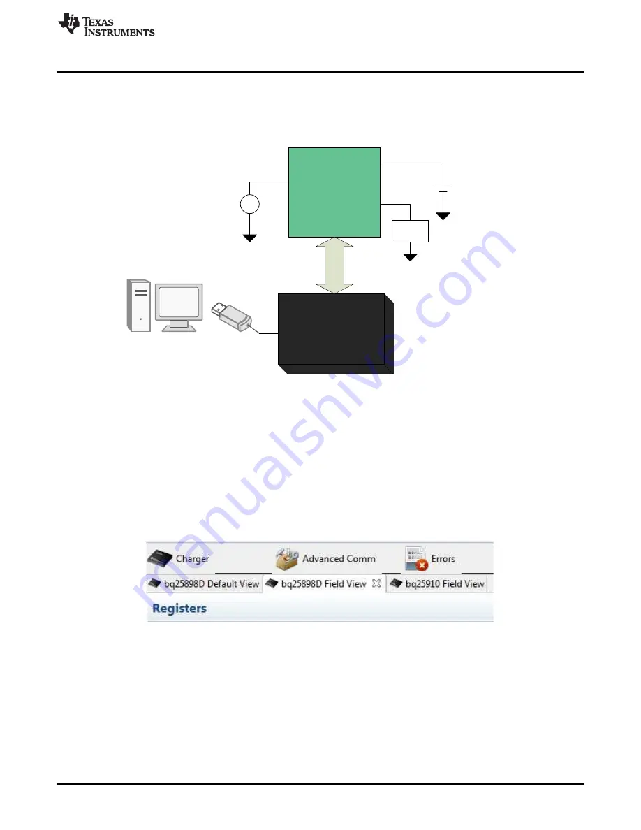
bq25910EVM
+
±
I2
C
GND
BAT
J4
VBUS
J3
GND
J5
SYS
J2
GND
Power Supply
Li-ion battery/
battery emulator
DC Load
www.ti.com
Test Setup and Results
5
SLVUB31A – September 2017 – Revised March 2018
Submit Documentation Feedback
Copyright © 2017–2018, Texas Instruments Incorporated
bq25910EVM-854 Evaluation Module
2.2
Test Setup
Both the master and parallel chargers are present on the EVM. This user's guide focuses on setting up
and evaluation of the bq25910 charger.
Figure 2
shows the connections between the power supplies, EV2400 and the bq25910EVM.
Figure 2. bq25910EVM Setup
2.2.1
Setting up the bq25898D
This user's guide covers the necessary steps to set up the master charger for parallel charger evaluation.
•
Connect the battery emulator to battery connector,
J4
. Set battery emulator to 3.8 V.
•
Using a 4-wire Molex cable (included with EV2400), connect the I2C port to the
J5
connector on the
EVM. Connect the USB cable to any USB port on the PC with bqStudio installed.
•
Apply 5 V at VBUS connector,
J3.
At this point, the bq25898D should be providing 2 A of charge
current to the battery.
•
Open bqStudio and select the
bq25910EVM
from the
Charger
menu.
Figure 3. bqStudio Device Tabs
•
The software allows you to modify both the bq25898D and bq25910 I2C registers.
Figure 3
shows the
device tabs on bqStudio. Selecting one of them opens the register interface for that particular device
and allows the values to be modified via I2C.
•
The DC electronic load can be connected at
J2
to emulate the system load. Note the 4-A maximum
output current of the converter and the maximum 6 A of continuous discharge current from the battery
of the bq25898D.
•
For full details on the test setup of the bq25898D, refer to
bq25898, bq25898D, and bq25898C
PWR730 Evaluation Module
.
•
To evaluate bq25910 only, place the bq25898D in HIZ mode.


