Texas Instruments BQ25883 Скачать руководство пользователя страница 8

V

VM#1

Windows 

PC

EV2300/

2400

Battery

Simulator 

or Power 

Supply

BS#1

VM#2

VM#3

V

VM#4

AGND

AGND

V

V

Resistive 

or e-Load

Load#1

V

VM#5

Test Summary

www.ti.com

8

SLUUC10 – February 2019

Submit Documentation Feedback

Copyright © 2019, Texas Instruments Incorporated

BQ25883 QFN boost-mode battery charger evaluation module

Advance Information

2.3

OTG Mode

2.3.1

OTG Mode Test Setup

Use the following list to set up the equipment for boost mode operation:

1. Ensure that the electronic load and battery simulator are turned off when connecting to the EVM.

Figure 3

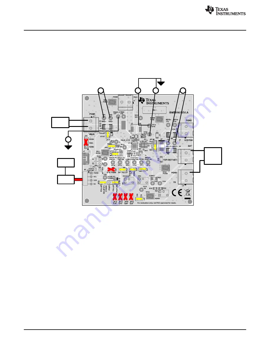
shows the test setup for BQ25883 when in OTG mode, including the jumper settings per

Table 2

.

Figure 3. BQ25883 OTG Mode Test Setup

2. Voltmeters 1 through 3 (VM1, VM2, and VM3) connect to Kelvin test points for measuring VBUS, SYS,

and BAT as close to the IC pins as possible. Voltmeters 4 through 5 measure the voltage across 0.01

Ω

, which gives the current.

3. Set BS#1 to 7.6 V and at a 6-A current limit, then turn off BS#1 and attach to the J4 (BAT, GND)

terminal of the EVM.

4. With electronic load disabled, attach to the J1 (VBUS, GND) terminal of the EVM.

5. With the EV2400 connected to the PC and the EVM, launch

Battery Management Studio

(bqStudio).

Select

Charger

and the BQ25883 evaluation software.

Содержание BQ25883

Страница 1: ...aluation module are synonymous with the BQ25883 QFN evaluation module unless otherwise noted Contents 1 Introduction 2 1 1 EVM Features 2 1 2 I O Descriptions 2 2 Test Summary 4 2 1 Equipment 4 2 2 Ch...

Страница 2: ...an onboard USB input adapter for connecting to a USB source and either communication through D D to set the default input current limit Use the EV2400 interface to program parameters for charge opera...

Страница 3: ...in to GND NA JP10 Pulls up STAT through diode and resistor to pullup source Installed JP11 Pulls up PG through diode and resistor to pullup source Shunt pins 2 and 1 JP12 Pull up SDA through 10 k resi...

Страница 4: ...Keithley 2420 Sourcemeter 3 Load 1 Electronic or resistive load capable of sinking up to 3 A at 9 2 V 4 Meters Six Fluke 75 multimeters equivalent or better Alternatively four equivalent voltage mete...

Страница 5: ...ff before connecting to the EVM Figure 1 BQ25883 Charge Mode Test Setup 2 Voltmeters 1 through 3 VM1 VM2 and VM3 connect to Kelvin test points for measuring VBUS SYS and BAT as close to the IC pins as...

Страница 6: ...PS 1 and click the Read Register button twice Observe everything Normal at the Fault box Observe D4 STAT is off because charge is disabled Observe D5 PG is on indicating power is good Measure on VM2 V...

Страница 7: ...ocumentation Feedback Copyright 2019 Texas Instruments Incorporated BQ25883 QFN boost mode battery charger evaluation module Advance Information 2 2 4 Charge Mode Evaluation Results Figure 2 shows the...

Страница 8: ...when connecting to the EVM Figure 3 shows the test setup for BQ25883 when in OTG mode including the jumper settings per Table 2 Figure 3 BQ25883 OTG Mode Test Setup 2 Voltmeters 1 through 3 VM1 VM2 an...

Страница 9: ...er OTG Voltage Limit 5 0 V OTG Current Limit 600 mA Deselect Enable Charge Deselect Enable HiZ if selected Select Enable OTG 2 3 3 OTG Mode Test Procedure Use the following steps for boost mode verifi...

Страница 10: ...between the power sources and power pins 3 PCB Layout Guidelines Minimize the switching node rise and fall times for minimum switching loss Proper layout of the components that minimize the high frequ...

Страница 11: ...uments Incorporated BQ25883 QFN boost mode battery charger evaluation module Advance Information 4 Board Layout Schematic and Bill of Materials 4 1 Board Layout Figure 5 through Figure 8 show the PCB...

Страница 12: ...PMID PMID 19 20 SW SW 15 16 13 14 BTST REGN 25 BQ25883RGE U1 STAT TS ILIM CD_ CE SDA_GND SCL_OTG D _PSEL D _ PG INT_VSET SW SW 10 0k R9 GND 1uH L1 22uF C5 22uF C12 10uF C6 IBUS up to 3A VSYS up to 8...

Страница 13: ...ny C1 1 0 01uF CAP CERM 0 01 uF 25 V 10 X7R 0402 0402 GCM155R71E103 KA37D MuRata C3 C4 2 22uF CAP CERM 22 uF 25 V 20 X5R 0805 0805 GRM21BR61E226 ME44L MuRata C7 C11 2 10uF CAP CERM 10 uF 25 V 20 X5R 0...

Страница 14: ...r 100mil 3x1 Tin TH Header 3 PIN 100mil Tin PEC03SAAN Sullins Connector Solutions JP2 JP3 JP5 JP6 JP7 JP10 JP13 JP14 JP15 9 Header 100mil 2x1 Tin TH Header 2 PIN 100mil Tin PEC02SAAN Sullins Connector...

Страница 15: ...Gold plated Black Shunt SNT 100 BK G Samtec 969102 0000 DA 3M TP1 TP2 TP3 TP4 TP5 TP6 TP9 TP10 TP12 TP13 TP16 TP17 TP19 TP20 TP21 TP22 16 Test Point Miniature White TH White Miniature Testpoint 5002 K...

Страница 16: ...P CERM 110 pF 25 V 5 C0G NP0 0402 0402 GRM1555C1E111J A01D MuRata C18 0 0 1uF CAP CERM 0 1 uF 16 V 10 X7R 0402 0402 GCM155R71C104 KA55D MuRata D1 D3 D6 0 20V Diode Schottky 20 V 1 A 152AD 152AD NSR10F...

Страница 17: ...0 25 W AEC Q200 Grade 0 1206 1206 CRCW120682R0J NEA Vishay Dale R26 0 39 2k RES 39 2 k 1 0 063 W AEC Q200 Grade 0 0402 0402 CRCW040239K2F KED Vishay Dale R27 0 75 0k RES 75 0 k 1 0 063 W AEC Q200 Gra...

Страница 18: ...18 SLUUC10 February 2019 Submit Documentation Feedback BQ25883 QFN boost mode battery charger evaluation module...

Страница 19: ...n and 3 ensuring your application meets applicable standards and any other safety security or other requirements These resources are subject to change without notice TI grants you permission to use th...

Страница 20: ...ther than TI b the nonconformity resulted from User s design specifications or instructions for such EVMs or improper system design or c User has not paid on time Testing and other quality control tec...

Страница 21: ...These limits are designed to provide reasonable protection against harmful interference in a residential installation This equipment generates uses and can radiate radio frequency energy and if not in...

Страница 22: ...instructions set forth by Radio Law of Japan which includes but is not limited to the instructions below with respect to EVMs which for the avoidance of doubt are stated strictly for convenience and s...

Страница 23: ...any interfaces electronic and or mechanical between the EVM and any human body are designed with suitable isolation and means to safely limit accessible leakage currents to minimize the risk of electr...

Страница 24: ...R DAMAGES ARE CLAIMED THE EXISTENCE OF MORE THAN ONE CLAIM SHALL NOT ENLARGE OR EXTEND THIS LIMIT 9 Return Policy Except as otherwise provided TI does not offer any refunds returns or exchanges Furthe...

Страница 25: ...e resources are subject to change without notice TI grants you permission to use these resources only for development of an application that uses the TI products described in the resource Other reprod...

Отзывы: