Test and Measurment Summary
3.1.4
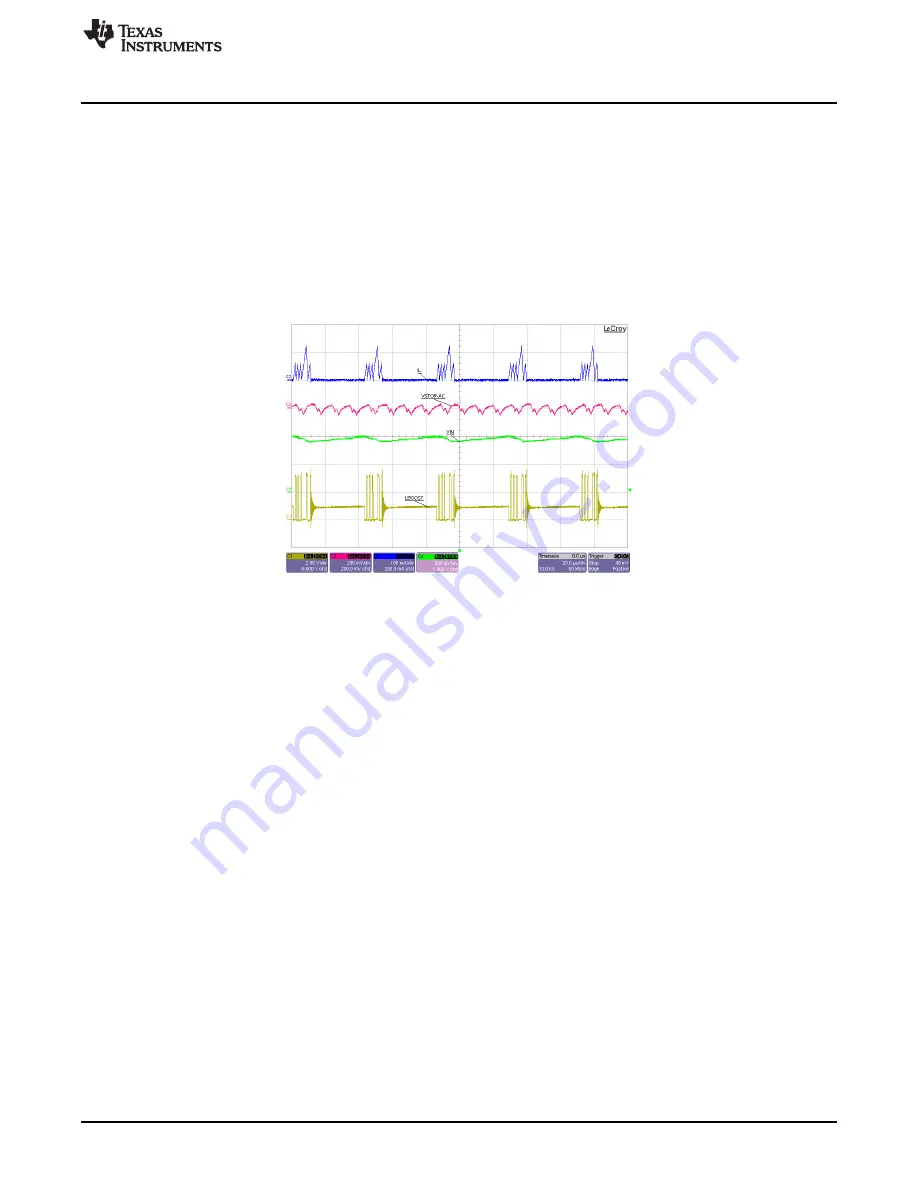
Charger Operation During Load Transient
The test setup is shown in
. The specific equipment used for the test results in
is listed
below:
1. VIN_DC, VBAT and VOUT are configured as explained in
.
2. The boost charger inductor current (IL) was measured by using an oscilloscope current probe across a
current loop that was inserted in series with inductor L1.
3. VSTOR's ripple voltage was measured using an oscilloscope voltage probe placed directly across the
VSTOR capacitor (C5). The scope probe's standard ground lead was replaced with very short lead.
4. VIN and the LBOOST pin (switching node of the boost charger) were measured by oscilloscope
voltage probes connected to TP1 and TP2.
Figure 9. Charger Operational Waveforms During 50-mA Load Transient
13
SLUUAA7A – July 2013 – Revised August 2014
User's Guide for bq25570 Battery Charger Evaluation Module for Energy
Harvesting
Copyright © 2013–2014, Texas Instruments Incorporated


