www.ti.com
Bill of Materials, Board Layout, and Schematics
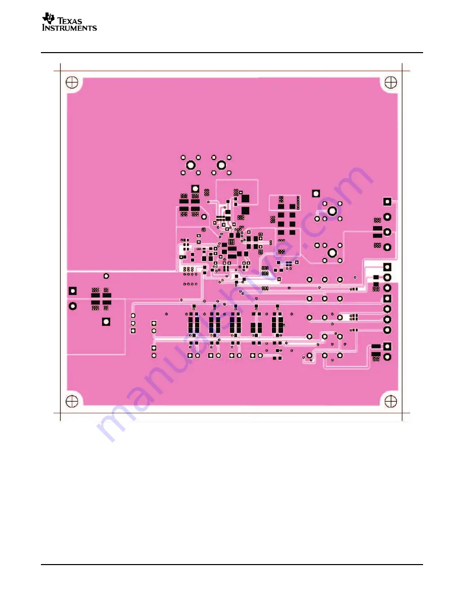
Figure 23. Layer 4
SLUU237 – January 2006
bq24720/21 EVM (HPA104) for Multi-Cell Synchronous
29
Switch-Mode Charger With System Power Selector and SMBus SBS-Like Interface
Страница 1: ...tware 8 5 The Software Main Window 9 6 The Software Main Window 10 7 The Software Main Window 11 8 The Waveforms at No Load 12 9 Test Setup for bq24720 EVM 13 10 Test Setup for bq24721 EVM 13 11 The S...
Страница 2: ...urrent to Li Ion or Li Pol applications The bq24720 21 has a highly integrated battery charge controller designed to work with external host commands The battery voltage charge current and other syste...
Страница 3: ...1 and 2 J5 1 2 Use external power supply as the pull up source are short circuited 2 3 Use REF5 as the pull up source J6 Enable charge process when ON Off The pull up power source supplies the LEDs w...
Страница 4: ...ied parameters A B If measured values are not within specified limits the unit under test has failed Observe A B Observe if A B occurs If they do not occur the unit under test has failed The assembly...
Страница 5: ...he supply 2 Connect the output of power supply number 1 in series with a current meter multimeter to J1 POS GND 3 Connect a voltage meter across J1 POS GND 4 Set the power supply number 2 for 3 3 V 10...
Страница 6: ...CIRCUIT V USB V EV2300 Iin I Power supply 1 BQ24720 EVM Oscilloscope L1 PH Test Summary 16 For bq24721 only Set the power supply number 3 for 2 5 V 100 mVDC 1 A 0 1 A current limit and then turn off t...
Страница 7: ...7 J7 J7 Power supply 2 ACGD J4 GND ALARM CHGEN SDA SCL POS J6 J6 J6 J5 D8 D10 D11 D7 D9 D18 J12 APPLICATION CIRCUIT V USB V EV2300 Iin I Power supply 1 BQ24721 EVM Oscilloscope L1 PH V Power supply 3...
Страница 8: ...he output voltage of PS1 until the D8 BYPASS is on The threshold is approximately 13 V Do not exceed Measure V TP ACDET 1 2 V 0 1 V Measure V J1 POS 13 V 1 V Measure V J8 VSYS 13 V 1 V Measure V TP VR...
Страница 9: ...indow and click Write This sets the battery voltage regulation threshold Type 1000 mA in the Charge Current Register on the lower right part of the window and click Write This sets the battery charge...
Страница 10: ...2 6 V 200 mV Observe D9 ALARM ON In the software main window click Read All on the top part of the window Observe D9 ALARM off Observe The B2 bit NoVreg of the Status Register turns green voltage loop...
Страница 11: ...indow Observe Make sure the phase node voltage PH and the inductor current waveforms look like Figure 8 SLUU237 January 2006 bq24720 21 EVM HPA104 for Multi Cell Synchronous 11 Switch Mode Charger Wit...
Страница 12: ...n on the Kepco load Connect the output of the electronic load in series with a current meter multimeter to J8 VSYS GND Make sure a voltage meter is connected across J8 VSYS GND Turn on the power of th...
Страница 13: ...ND VSYS J8 GND VBAT IOUT GND REF J3 J2 J11 J10 J9 J7 Power supply 2 ACGD J4 GND ALARM CHGEN SDA SCL POS J6 J5 D8 D10 D11 D7 D9 APPLICATION CIRCUIT Isys V I USB V EV2300 Electr Load Kepco Load Iin I Po...
Страница 14: ...ent output If not change it to 1 Click Write Measure V J4 IOUT 600 mV 30 mV Click Read All Observe The B3 bit NoIreg of the Status Register turns green charge current loop active The window should be...
Страница 15: ...nic load Measure I sys 2500 mA 200 mA I bat 500 mA 300 mA II 3000 mA 400 mA Measure V J4 IOUT 100 mV 80 mV Change the B3 bit IOUTBT of the Control Register to 0 adapter current output Click Write Meas...
Страница 16: ...sure V J8 ACGD 1 465 V 300 mV Slowly increase the output voltage of PS3 to 2 5 V 100 mV Measure I bat 3000 mA 200 mA 2 4 5 Voltage Regulation and NonSynchronous Operation at Light Load Slowly increase...
Страница 17: ...ndow Observe The inductor current waveform is like Figure 15 The inductor current does not drop below 0 A SLUU237 January 2006 bq24720 21 EVM HPA104 for Multi Cell Synchronous 17 Switch Mode Charger W...
Страница 18: ...r to 1 disable the charging Click Write Change the B4 bit LEARN of the Control Register to 1 learn cycle Click Write Measure V J8 VSYS 12 3 V 300 mV battery connected to system Observe D10 ACSW ON off...
Страница 19: ...10 ACSW ON ON D11 BATDRV ON OFF Turn off PS1 Measure V J8 VSYS 12 3 V 300 mV battery connected to system Observe D10 ACSW ON OFF D11 BATDRV ON ON D8 BYPASS ON OFF Observe The B1 bit CHGOFF of the Stat...
Страница 20: ...ti com Test Summary Figure 17 The Software Main Window bq24720 21 EVM HPA104 for Multi Cell Synchronous 20 SLUU237 January 2006 Switch Mode Charger With System Power Selector and SMBus SBS Like Interf...
Страница 21: ...gh side gate resistor R17 must be lower than 5 to assure the break before make 1 The control stage and the power stage are layed out separately At each layer the signal ground and the power ground are...
Страница 22: ...ND Liteon 1 1 J1 Terminal Block 2 pin 15 A 5 1 mm 0 40 0 35 ED1609 OST 1 1 J2 Terminal Block 2 pin 6 A 3 5 mm 75525 ED1514 OST 1 1 J3 Terminal Block 4 pin 6 A 3 5 mm 0 55 0 25 ED1516 OST 1 1 J4 Termin...
Страница 23: ...X 6 32 NYL 0 500 sf_thvt_325_rnd 4816 Keystone ST4 TP1 TP2 TP3 TP4 TP5 TP6 TP13 TP14 TP19 TP22 18 18 5002 Test Point White Thru Hole Color Keyed 0 100 0 100 5002 Keystone TP24 TP26 TP27 TP29 TP31 TP32...
Страница 24: ...yout Bill of Materials Board Layout and Schematics Figure 18 Top Assembly 24 bq24720 21 EVM HPA104 for Multi Cell Synchronous SLUU237 January 2006 Switch Mode Charger With System Power Selector and SM...
Страница 25: ...of Materials Board Layout and Schematics Figure 19 Bottom Assembly SLUU237 January 2006 bq24720 21 EVM HPA104 for Multi Cell Synchronous 25 Switch Mode Charger With System Power Selector and SMBus SBS...
Страница 26: ...ill of Materials Board Layout and Schematics Figure 20 Layer 1 26 bq24720 21 EVM HPA104 for Multi Cell Synchronous SLUU237 January 2006 Switch Mode Charger With System Power Selector and SMBus SBS Lik...
Страница 27: ...ill of Materials Board Layout and Schematics Figure 21 Layer 2 SLUU237 January 2006 bq24720 21 EVM HPA104 for Multi Cell Synchronous 27 Switch Mode Charger With System Power Selector and SMBus SBS Lik...
Страница 28: ...ill of Materials Board Layout and Schematics Figure 22 Layer 3 28 bq24720 21 EVM HPA104 for Multi Cell Synchronous SLUU237 January 2006 Switch Mode Charger With System Power Selector and SMBus SBS Lik...
Страница 29: ...ill of Materials Board Layout and Schematics Figure 23 Layer 4 SLUU237 January 2006 bq24720 21 EVM HPA104 for Multi Cell Synchronous 29 Switch Mode Charger With System Power Selector and SMBus SBS Lik...
Страница 30: ...Board Layout and Schematics Figure 24 Top Silk The schematic is shown on the following pages 30 bq24720 21 EVM HPA104 for Multi Cell Synchronous SLUU237 January 2006 Switch Mode Charger With System P...
Страница 31: ......
Страница 32: ......
Страница 33: ...the user s responsibility to take any and all appropriate precautions with regard to electrostatic discharge EXCEPT TO THE EXTENT OF THE USER S INDEMNITY OBLIGATIONS SET FORTH ABOVE NEITHER PARTY SHAL...
Страница 34: ...ute a license from TI to use such products or services or a warranty or endorsement thereof Use of such information may require a license from a third party under the patents or other intellectual pro...