


7.1
Connecting the bq20z40/bq29330/bq29412 Circuit Module to a Battery Pack
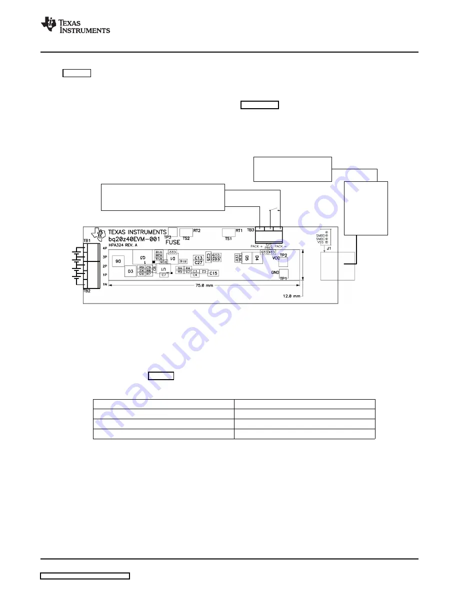
+
-
LOAD/CHARGER
EV2300
COMPUTER
USB
SMBus
cable
+
-
SMB
7.2
PC Interface Connection
www.ti.com
Hardware Connection
shows how to connect the bq20z40/bq29330/bq29412 circuit module to the cells and system
load/charger.
The cells must be connected in the following order:
1. 4-Cell Pack: 1N (BAT-), 1P, 2P, 3P, then 4P (see
for definitions).
2. 3-Cell Pack: 1N (BAT-), 1P, 2P, and then connect 4P and 3P together.
3. 2-Cell Pack: 1N (BAT-), 1P, and then connect 4P, 3P, and 2P together
To start charge or discharge test, connect SYS PRES pin to PACK- pin to set SYS PRES state. To test
sleep mode, disconnect the SYS PRES pin.
Figure 7. bq20z40/bq29330 Circuit Module Connection to Cells and System Load/Charger
The following steps configure the hardware for interface to the PC:
1. Connect the bq20z40/bq29330-based smart battery to the EV2300 using the provided cable or the
connections shown in
.
Table 4. Circuit Module to EV2300 Connections
bq20z40/bq29330-Based Battery
EV2300
SMBD
SMBD
SMBC
SMBC
VSS
GND
2. Connect the PC USB cable to the EV2300 and the PC USB port.
The bq20z40EVM-001 is now set up for operation.
SLUU320C – January 2009 – Revised June 2009
bq20z40EVM-001 SBS 1.1 Impedance Track™Technology
9
Enabled Battery Management Solution EVM