Hardware
11
SWRU521A – May 2017 – Revised December 2017
Copyright © 2017, Texas Instruments Incorporated
IWR1642 Evaluation Module (IWR1642BOOST) Single-Chip mmWave
Sensing Solution
2.5
Connecting the BoosterPack to the LaunchPad or the MMWAVE-DEVPACK
The development pack may be required with the BoosterPack for the following use cases:
•
Connecting to Radar Studio
Radar Studio is a tool that provides capability to configure the mmWave front end from the PC. This
tool is available in the
•
Capturing high-speed LVDS data using the SW1400 FPGA platform from TI (see
Capture and Pattern Generation Platform
).
The TSW1400 FPGA platform allows users to capture the raw ADC data over the high-speed debug
interface and post process it in the PC.
•
Getting DSP trace data through the MIPI 60-pin interface
•
Use the DMM interface
This BoosterPack can be stacked on top of the Launchpad or the
by using the two
20-pin connectors. The connectors do not have a key to prevent the misalignment of the pins or reverse
connection. Hence, care must be taken to ensure reverse mounting does not take place.
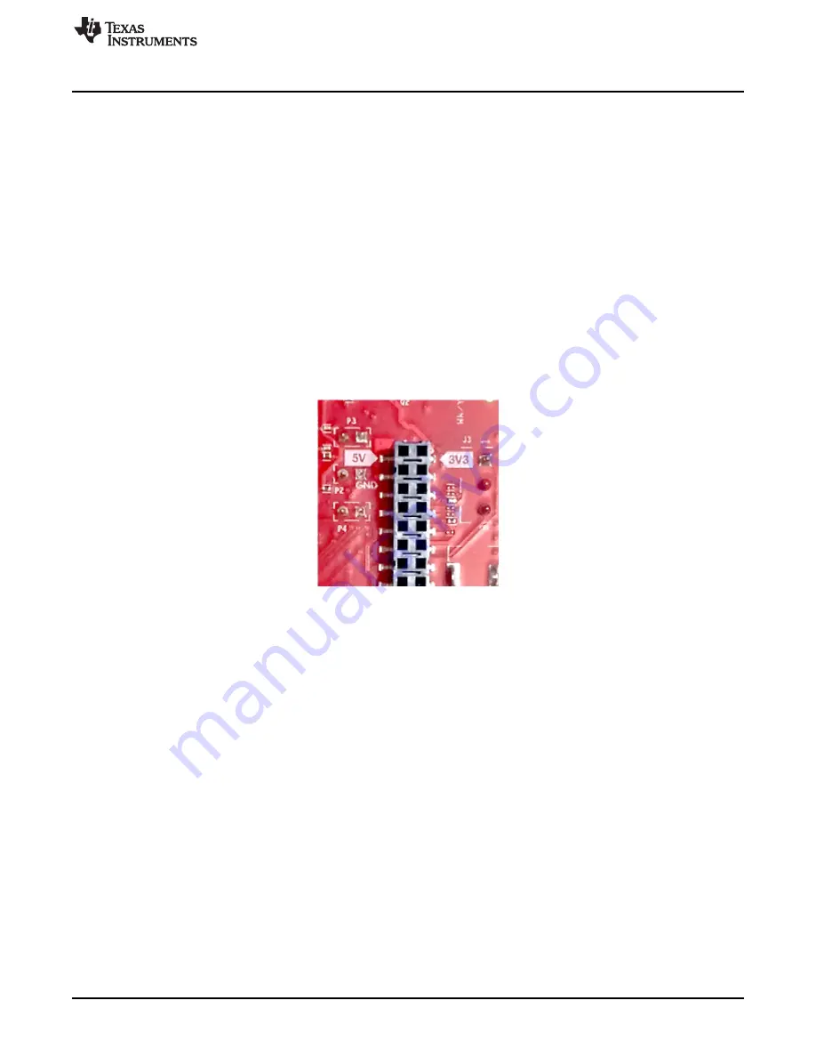
On the IWR1642 BoosterPack, TI has provided 3V3 markings near pin 1, shown in
. The same
marking is provided on compatible LaunchPads (must be aligned before powering up the boards).
Figure 8. 3V3 and 5V Marking on BoosterPack
For details on these use cases, see the
2.6
Antenna
The BoosterPack includes onboard-etched antennas for the four receivers and two transmitters that
enable tracking multiple objects with their distance and angle information. This antenna design enables
estimation of distance and elevation angle that enables object detection in a two-dimensional plane.
shows the PCB antennas.


