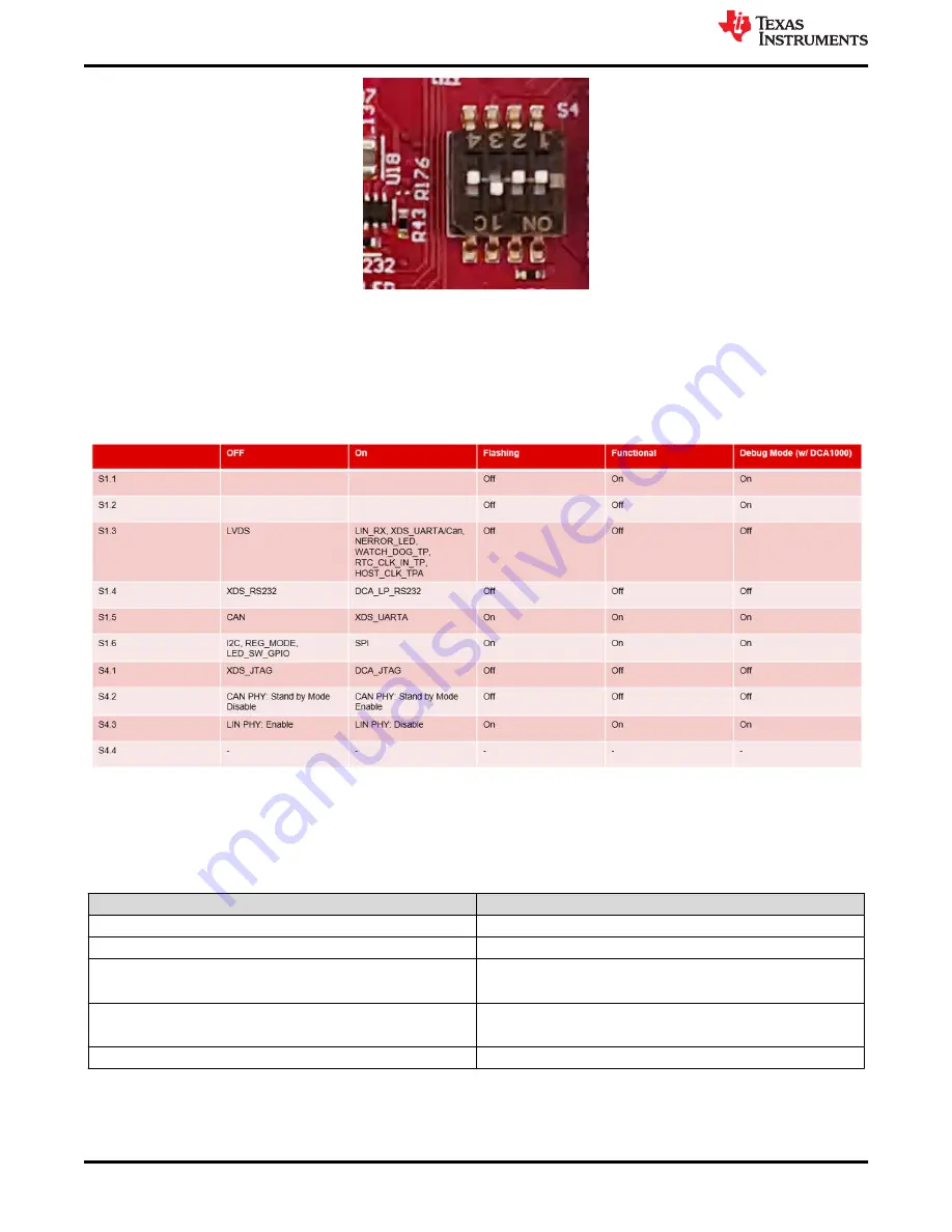
Figure 6-6. S4 Switch for Various mode Settings
provides the different boot mode configurations to the device. Device supports application mode,
QSPI flashing mode (Device management mode), and debug modes. This mode (SOP) configuration shown
below in
must be exercised first. After the SOP settings nRESET need to be issued to register the
SOP settings.
also provides the switch position for different modes of operation supported by the
device and EVM.
Figure 6-7. SOP Switches
6.3 LEDs
contains the list of LEDs on the XWRL6432BOOST.
Table 6-1. List of LEDs
LED reference designators
Description
D6
5V Power indication
D5
Reset LED.
D9
NERROR LED
Note: There is switch settings are needed to enable this.
D7
User LED: Customer programmable.
Note: There is switch settings are needed to enable this.
D3
Power good indication
XWRL6432BOOST Antenna
12
IWRL6432BOOST/AWRL6432BOOST EVM: FR4-Based Low Power 60 GHz
mm-Wave Sensor EVM User Guide
Copyright © 2022 Texas Instruments Incorporated


