AMIC110
SPI
JTAG
UART0
McASP1_AXR0_MDRB
McASP1_AXR1_MDXB
McASP1_ACLKR_MCLKXB
McASP1_ACLKX_MCLKXB
McASP1_FSR_MDRB
McASP
SPI_D1_McASP1_FSX_MFSRB
SPICLK
SPI_D1
SPICS
SPI_D0
DDR3
EEPROM
Board ID
DDR3 is not required when the EtherCAT slave stack
runs on the host controller (for example: C2000).
SPI
ECAT_LATCH0
ECAT_LATCH1
ECAT_SYNC0
ECAT_SYNC1
IRQ
Firmware_Loaded
SYS_RESETn
EC
AT
a
n
d
Sys
UART1_TX
UART1_RX
UART1_DE
I/
O
co
n
n
e
ct
io
n
s
F
a
il-
sa
fe
I
/O
(
3
.3
V
)
C2000
TM
MCU with
EtherCAT stack and
driver for ET1100
SPI Flash
JTAG
header
3.3-V TTL,
fail-safe I/O
Header
6-pin header for
3.3-V TTL serial-
to-USB cable
PMIC
TPS650250
DC jack
Input: 5 V
EMI filter
3V3
1V8
1V5
1V1
10/100 Mbps
Ethernet PHY1
DP83822
10/100 Mbps
Ethernet PHY2
DP83822
Ma
g
n
e
ti
cs
RJ45
Status LEDs
Ma
g
n
e
ti
cs
RJ45
Status LEDs
Status LED per
EtherCAT standard
requirements
Jack with external
magnetics
Copyright © 2017, Texas Instruments Incorporated
3V3
PR
O
F
IBU
S
Introduction
3
SPRUIE6 – April 2017
Copyright © 2017, Texas Instruments Incorporated
AMIC110 Industrial Communications Engine (AMIC110 ICE)
1.2
Functional Block Diagram
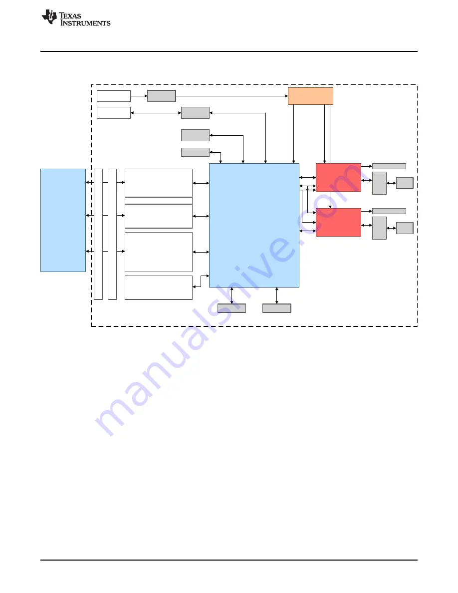
shows the functional block diagram of the AMIC110 ICE device.
Figure 1. AMIC110 ICE Functional Block Diagram
1.3
Basic Operation
For detailed information and resources on the AMIC110 ICE, see
Follow the steps in
and
to quickly get started with the AMIC110 ICE.
1.3.1
Hardware Setup
See the following steps to set up the hardware of the AMIC110 ICE.
1. Unbox the AMIC110 ICE and identify the components and connectors detailed in
.
2. Connect a 20-pin JTAG emulator to J1 on the AMIC110 ICE (see
) to download a bootable
image to the onboard SPI Flash. For example, XDS100 or XDS200 emulators may be used for this
purpose and are available at
and
.


