background image

4.2 Launching the Software

After installation, a shortcut to launch the GUI can be found in the 

Start

 menu. If installed in the default directory, 

the AFE881H1EVM software can also be launched by navigating to the 

Texas Instruments

 folder in the 

Program 

Files (x86)

 directory, as 

Figure 4-2

 shows.

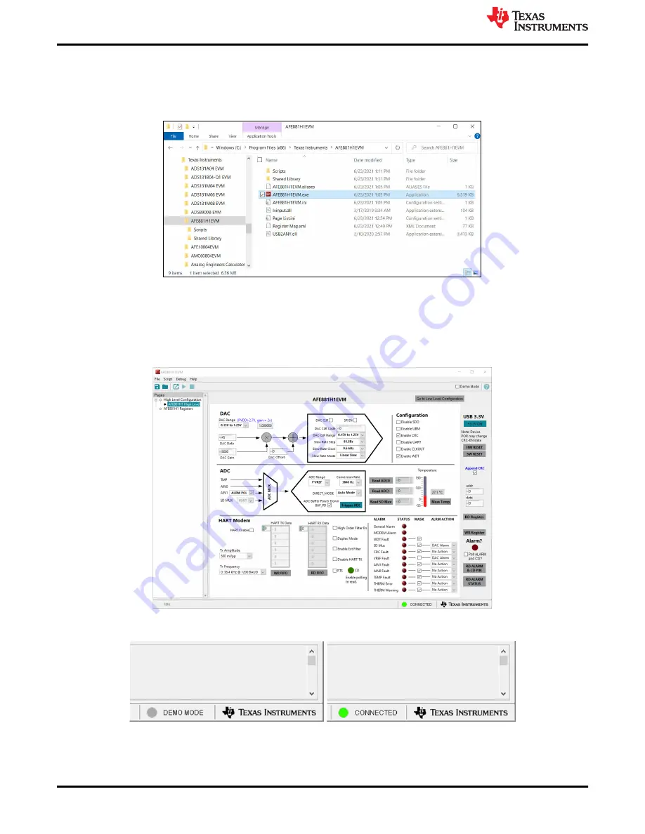
Figure 4-2. Launching the AFE881H1EVM GUI

Figure 4-3

 shows the GUI after launch. If the USB2ANY controller is not connected to the PC when the software 

is launched, the GUI defaults to 

demo

 mode. 

Figure 4-4

 illustrates the bottom-left corner of the GUI showing 

the hardware connection status: DEMO MODE or CONNECTED. After the USB2ANY controller is properly 
connected to the PC, close and reopen the AFE881H1EVM software to detect the device.

Figure 4-3. AFE881H1EVM GUI at Launch

Figure 4-4. USB2ANY Digital Controller Connection Status

Software Overview

www.ti.com

12

AFE881H1 Evaluation Module

SLAU858 – NOVEMBER 2021

Submit Document Feedback

Copyright © 2021 Texas Instruments Incorporated

Содержание AFE881H1

Страница 1: ...s 1 Overview 3 1 1 Kit Contents 3 1 2 Related Documentation From Texas Instruments 3 2 USB2ANY Interface Adapter 4 2 1 Signal Definitions for J10 4 2 2 USB2ANY Theory of Operation 5 3 EVM Hardware Overview 6 3 1 Electrostatic Discharge Caution 6 3 2 EVM Block Diagram 6 3 3 EVM Jumper Summary 7 3 4 Terminal and Pin Definitions 8 3 5 Connecting the USB2ANY 9 3 6 Connecting the USB Cable to the USB2A...

Страница 2: ...ipt Window 14 Figure 4 8 Scripting Tool Recording a Macro 15 Figure 4 9 Deselecting App Execution Aliases 15 Figure 5 1 AFE881H1EVM Schematic 16 Figure 5 2 AFE881H1EVM PCB Top Layer Layout 17 Figure 5 3 AFE881H1EVM PCB Mid Layer 1 Layout 17 Figure 5 4 AFE881H1EVM PCB Mid Layer 2 Layout 18 Figure 5 5 AFE881H1EVM PCB Bottom Layer Layout 18 List of Tables Table 1 1 AFE881H1EVM Kit Contents 3 Table 1 ...

Страница 3: ...exas Instruments The documents in Table 1 2 provides information regarding Texas Instruments integrated circuits used in the assembly of the AFE881H1EVM This user s guide is available from the TI web site under literature number SLAU858 Any letter appended to the literature number corresponds to the document revision that is current at the time of the writing of this document Newer revisions may b...

Страница 4: ...gnal Definition 4 6 8 16 27 28 GND Ground 11 ALARM Alarm notification open drain When an alarm occurs this pin is held low Otherwise this pin goes to Hi Z 12 CS SPI communication for AFE881H1 chip select 13 MISO SPI communication for AFE881H1 digital output 14 MOSI SPI communication for AFE881H1 digital input 15 3p3V 3 3 V supply voltage 17 CD Carrier detect A logic high on this pin indicates a va...

Страница 5: ...ls of operation are included in the USB2ANY Interface Adapter User s Guide Power Management 14 MSP430F5529 Switchable 12C pullups 4 3 3 V 5 0 V DAC1 DAC2 GPIO 12C PWM and other interfaces shared lines Analog Inputs Ext VREF Figure 2 2 USB2ANY Interface Adapter Block Diagram www ti com USB2ANY Interface Adapter SLAU858 NOVEMBER 2021 Submit Document Feedback AFE881H1 Evaluation Module 5 Copyright 20...

Страница 6: ...roved ESD workstation 3 2 EVM Block Diagram A block diagram of the EVM hardware setup is shown in Figure 3 1 This board provides connections and test points for the SPI and UART communication power reference ground connections ADC inputs HART modem and the analog output of the DAC AFE881H1 USB2ANY Connector Bus Transceiver Level Shifter SPI Connections UART CD RTS ALARM Connections PVDD Supply Opt...

Страница 7: ...ult Open 1 2 UART_IN disconnected from bus transceiver J13 POL SEL Short 1 2 POL_SEL connected to PVDD through 100 kΩ resistor Short 2 3 POL_SEL connected to GND through 100 kΩ resistor default J14 Resistor Load Short 1 2 VOUT connected to 10 kΩ load Open 1 2 VOUT no resistive load default J17 Cap Load Short 1 2 VOUT connected to 100 pF load Open 1 2 VOUT no capacitive load default J19 J20 FILT SE...

Страница 8: ...ect UARTIN to device from USB2ANY through voltage level shifter J9 SPI Conn Pin 1 RESET Pin 3 SCLK Pin 5 SDI Pin 7 CS Pin 9 SDO Pin 2 4 6 8 10 GND J10 USB2ANY 30 pin ribbon cable connection see Table 2 1 J11 ADC Terminal 1 AIN0 Terminal 2 GND Terminal 3 AIN1 J12 UART Conn Pin 1 UART_IN Pin 3 UART_OUT Pin 5 RTS Pin 7 CD Pin 9 ALARM Pin 2 4 6 8 10 GND J13 POL_SEL Shunt 1 2 Pull up to PVDD Shunt 2 3 ...

Страница 9: ...ting the USB2ANY To connect the EVM board and the USB2ANY Interface Adapter together firmly slide the cable ends of the 30 pin ribbon cable into the USB2ANY Interface Adapter and the AFE881H1EVM as shown in Figure 3 4 Make sure that the connectors are completely pushed together Loose connections between the USB2ANY and the EVM may cause intermittent operation USB2ANY AFE881H1EVM Figure 3 4 USB2ANY...

Страница 10: ...e used disconnect the supply connection from the 3p3V line coming from the USB2ANY before attaching external supplies 3 7 Optional EVM Operations This section describes the various operational options that can be used by the EVM 3 7 1 Power Configuration The default configuration of the AFE881H1EVM allows the board to be powered from the 3p3V line coming from the USB2ANY Jumper J3 connects power f...

Страница 11: ...ware files and drivers to the local machine The AFE881H1EVM installer installs all the driver files necessary to operate the USB2ANY controller Choose the destination directory for the GUI software accept the license agreements and follow the on screen instructions shown in Figure 4 1 to complete the installation Figure 4 1 AFE881H1EVM Software Installation Prompts To use the scripting tool the Py...

Страница 12: ... controller is not connected to the PC when the software is launched the GUI defaults to demo mode Figure 4 4 illustrates the bottom left corner of the GUI showing the hardware connection status DEMO MODE or CONNECTED After the USB2ANY controller is properly connected to the PC close and reopen the AFE881H1EVM software to detect the device Figure 4 3 AFE881H1EVM GUI at Launch Figure 4 4 USB2ANY Di...

Страница 13: ...ess to registers The Register Map section in the center of the page lists all the registers grouped by the pages in the device Directly above the Register Map section are four buttons that allow read and write access to all registers The Field View section on the right side of the page shows the various fields in the currently selected register Select a register name to highlight the register The ...

Страница 14: ...ure 4 6 AFE881H1 High Level Tab 4 3 3 Using the Python Scripting Tool The AFE881H1EVM software provides a scripting tool to automate register reads and writes for reuse To use the scripting tool the Python programming environment must be installed Download the latest x86 version of Python 2 7 at https www python org downloads To launch the scripting tool click Script Launch Window as shown in Figu...

Страница 15: ... window does not appear check the settings for application execution aliases To do so open the Windows Settings and then select Apps In the resulting Apps window select Apps features and then click on the Manage app execution aliases link The next page loads a list of apps Deselect both application installers for python exe and python3 exe Figure 4 9 shows the windows settings for managing applica...

Страница 16: ...tic The AFE881H1EVM schematic is shown in Figure 5 1 Figure 5 1 AFE881H1EVM Schematic Schematics PCB Layout and Bill of Materials www ti com 16 AFE881H1 Evaluation Module SLAU858 NOVEMBER 2021 Submit Document Feedback Copyright 2021 Texas Instruments Incorporated ...

Страница 17: ...the AFE881H1EVM Figure 5 2 AFE881H1EVM PCB Top Layer Layout Figure 5 3 AFE881H1EVM PCB Mid Layer 1 Layout www ti com Schematics PCB Layout and Bill of Materials SLAU858 NOVEMBER 2021 Submit Document Feedback AFE881H1 Evaluation Module 17 Copyright 2021 Texas Instruments Incorporated ...

Страница 18: ...er 2 Layout Figure 5 5 AFE881H1EVM PCB Bottom Layer Layout Schematics PCB Layout and Bill of Materials www ti com 18 AFE881H1 Evaluation Module SLAU858 NOVEMBER 2021 Submit Document Feedback Copyright 2021 Texas Instruments Incorporated ...

Страница 19: ...TVS Bi 5 5 V 14 Vc 1x0 6mm 1x0 6mm ESD105B102ELE6327XTMA1 Infineon Technologies H1 H2 H3 H4 4 Machine Screw Round 4 40 x 1 4 Nylon Philips panhead Screw NY PMS 440 0025 PH B F Fastener Supply H5 H6 H7 H8 4 Standoff Hex 0 5 L 4 40 Nylon Standoff 1902C Keystone J1 J6 J8 J14 J16 J17 6 Header 100mil 2x1 Tin TH Header 2x1 100mil TH 5 146278 2 TE Connectivity J2 J4 J18 3 Standard Banana Jack Uninsulated...

Страница 20: ...d TH Red Miniature Testpoint 5000 Keystone U2 1 8 Bit Dual Supply Bus Transceiver with Configurable Voltage Level Shifting and Three State Outputs DB0024A SSOP 24 DB0024A SN74LVC8T245DBR Texas Instruments U4 1 16 Bit Low Power DACs With Internal HART Modem Voltage Reference and Diagnostic ADC for 4 20mA Loop Powered Applications UQFN24 UQFN24 AFE881H1RRUT Texas Instruments U3 U5 2 2 Bit Dual Suppl...

Страница 21: ...other than TI b the nonconformity resulted from User s design specifications or instructions for such EVMs or improper system design or c User has not paid on time Testing and other quality control techniques are used to the extent TI deems necessary TI does not test all parameters of each EVM User s claims against TI under this Section 2 are void if User fails to notify TI of any apparent defects...

Страница 22: ... These limits are designed to provide reasonable protection against harmful interference in a residential installation This equipment generates uses and can radiate radio frequency energy and if not installed and used in accordance with the instructions may cause harmful interference to radio communications However there is no guarantee that interference will not occur in a particular installation...

Страница 23: ...y for convenience and should be verified by User 1 Use EVMs in a shielded room or any other test facility as defined in the notification 173 issued by Ministry of Internal Affairs and Communications on March 28 2006 based on Sub section 1 1 of Article 6 of the Ministry s Rule for Enforcement of Radio Law of Japan 2 Use EVMs only after User obtains the license of Test Radio Station as provided in R...

Страница 24: ... any interfaces electronic and or mechanical between the EVM and any human body are designed with suitable isolation and means to safely limit accessible leakage currents to minimize the risk of electrical shock hazard User assumes all responsibility and liability for any improper or unsafe handling or use of the EVM by User or its employees affiliates contractors or designees 4 4 User assumes all...

Страница 25: ...OR DAMAGES ARE CLAIMED THE EXISTENCE OF MORE THAN ONE CLAIM SHALL NOT ENLARGE OR EXTEND THIS LIMIT 9 Return Policy Except as otherwise provided TI does not offer any refunds returns or exchanges Furthermore no return of EVM s will be accepted if the package has been opened and no return of the EVM s will be accepted if they are damaged or otherwise not in a resalable condition If User feels it has...

Страница 26: ...o change without notice TI grants you permission to use these resources only for development of an application that uses the TI products described in the resource Other reproduction and display of these resources is prohibited No license is granted to any other TI intellectual property right or to any third party intellectual property right TI disclaims responsibility for and you will fully indemn...

Отзывы: