Texas Instruments ADS8861EVM-PDK Скачать руководство пользователя страница 6

EVM Digital Interface

www.ti.com

3

EVM Digital Interface

Samtec part numbers SSW-110-22-F-D-VS-K and TSM-110-01-L-DV-P provide convenient 10-pin, dual-
row, header and socket combinations at P1. The header and socket provides access to the ADC digital
control pins. Consult Samtec at

www.samtec.com

or call 1-800-SAMTEC-9 for a variety of mating

connector options.

Table 3

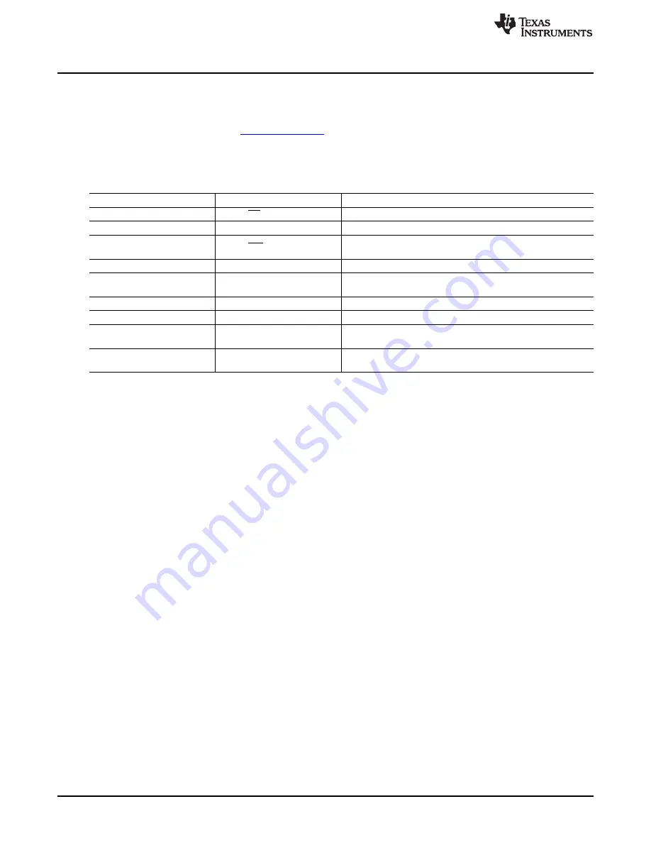
summarizes the pinouts for the digital interface J2.

Table 3. J2: Serial Interface Header

Pin Number

Signal

Description

J2.1

CS or CONVST

Chip-select input that can be used as a convert start

J2.3

SCLK

Serial clock input

Chip-select input that can be used as a convert start intended for

J2.7

CS or CONVST

the MMB0 motherboard

J2:13

SDO or MISO

SDO or MISO output

20-k

Ω

pull-up resistor for detecting falling edges at the end of

J2.15

INT

conversions

J2.17

CONVST

Directly connects to the convert start pin if JP3 is installed

J2.4, J2.10, and J2.18

GND

Digital ground connections

I

2

C bus; used only used to program the U4 EEPROM on the

J2.16, J2.20

I

2

C™ bus

EVM board

J2.2, J2.5-6, J2.8-9, J2.11-12,

Unused

Unused

J2.14, and J2:19

3.1

Serial Interface (SPI)

The ADS8861 ADC uses SPI serial communication in mode 1 (CPOL = 0, CPHA = 1) with high-speed
clocks greater than 30 MHz or uses mode 0 (CPOL = 0, CPHA = 0) for slower clocks. Because the serial
clock (SCLK) frequency can be as fast as 80 MHz, the ADS8861EVM offers 47-

Ω

resistors between the

SPI signals and J2 to aid with signal integrity. Typically, in high-speed SPI communication, fast signal
edges can cause overshoot; these 47-

Ω

resistors slow down the signal edges in order to minimize signal

overshoot.

3.2

I

2

C Bus for Onboard EEPROM

The ADS8861EVM has an I

2

C bus that records the board name and assembly date to communicate with

the onboard EEPROM. This bus is not used in any form by the ADS8861 converter.

6

ADS8861EVM-PDK

SBAU214 – October 2013

Submit Documentation Feedback

Copyright © 2013, Texas Instruments Incorporated

Содержание ADS8861EVM-PDK

Страница 1: ...ghter card MMB0 motherboard A to B USB cable and 6 V wall adapter power supply This user s guide covers the circuit description schematic diagram and bill of materials for the ADS8861EVM daughter card...

Страница 2: ...ion 8 6 Plug In Installer 9 7 MMB0 Motherboard Jumper Configuration 10 8 ADS8861EVM Jumper Configuration 11 9 Loading EVM Plug in 12 10 ADS8861EVM Plug In Device Configuration Tab 13 11 ADCPro Test Pl...

Страница 3: ...ftware User s Guide SBAU128 available for download from www ti com ADS8861EVM Daughter Board Features Includes support circuitry as a design example to match ADC performance 3 3 V slave serial periphe...

Страница 4: ...MA analog inputs Table 2 SMA Analog Inputs Pin Number Signal Description Channel 0 negative differential input This pin can be grounded for single J4 A0 ended signals J5 A0 Channel 0 positive differen...

Страница 5: ...ence voltage should be below 5 V because the EVM is powered by a 5 V analog supply This EVM uses a 4 5 V value created by the onboard REF5045 This value is then filtered by an RC filter with a 160 Hz...

Страница 6: ...t start pin if JP3 is installed J2 4 J2 10 and J2 18 GND Digital ground connections I2 C bus used only used to program the U4 EEPROM on the J2 16 J2 20 I2 C bus EVM board J2 2 J2 5 6 J2 8 9 J2 11 12 U...

Страница 7: ...V analog power supply connected to J3 3 The ADS8861 is limited to 3 6 V as an analog supply Therefore the board regulates down the 5 V analog supply with an onboard 3 3 V LDO TPS78833 4 2 Digital Pow...

Страница 8: ...tialize conversions The rising edge of the chip select signal starts a conversion then after the conversion time the falling edge of chip select brings the digital output out of 3 state Figure 4 shows...

Страница 9: ...Installing the ADCPro Software ADCPro is the primary program used to evaluate the ADS8861 ADCPro is available for download at www ti com tool adcpro Refer to the ADCPro User s Guide SBAU128 for detai...

Страница 10: ...J13A to open and J13B to closed on the MMB0 as shown in Figure 7 Figure 7 MMB0 Motherboard Jumper Configuration J12 must be closed This setting allows the wall supply to power up the MMB0 and the ADS8...

Страница 11: ...d verify that J12 is closed on the MMB0 motherboard 7 PDK Kit Operation The evaluation software is based on ADCPro This program operates using a variety of plug ins To use ADCPro load an EVM plug in a...

Страница 12: ...Load the ADS886XEVM plug in from the ADCPro drop down EVM menu as shown in Figure 9 Note that only one EVM plug in can be loaded at a time If a different plug in is selected the previous plug in is u...

Страница 13: ...CLK sets the clock frequency used by the SPI interface to capture data SCLK should be between 70 MHz to 80 MHz for 1 MSPS For slow sampling rates use 10 MHz Do not use SCLK frequencies between 30 MHz...

Страница 14: ...ired test scenario press the Acquire button to start the data collection process the software collects the number of data points specified in the Test plug in Block Size control While acquiring data t...

Страница 15: ...2 pin 100 Gold 1x2 Samtec TSW 102 07 L S 16 7 R1 R2 R20 R24 R26 R34 R36 Not Installed 17 4 1k R3 R4 R5 R6 Resistor Thin Film Chip 0 1 1 10W 0603 Panasonic ERA 3AEB102V 18 5 10 R7 R10 R22 Resistor Thi...

Страница 16: ...ayouts are not to scale These figures are intended to show how the board is laid out these figures are not intended to be used for manufacturing ADS8861EVM PCBs Figure 12 ADS8861EVM PCB Top Layer Figu...

Страница 17: ...aterials Schematics and Layout Figure 14 ADS8861EVM PCB Power Layer Figure 15 ADS8861EVM PCB Bottom Layer 17 SBAU214 October 2013 ADS8861EVM PDK Submit Documentation Feedback Copyright 2013 Texas Inst...

Страница 18: ...of Materials Schematics and Layout www ti com 8 3 Schematic Figure 16 ADS8861EVM Schematic 18 ADS8861EVM PDK SBAU214 October 2013 Submit Documentation Feedback Copyright 2013 Texas Instruments Incorpo...

Страница 19: ...o handling the product This notice contains important safety information about temperatures and voltages For additional information on TI s environmental and or safety programs please contact the TI a...

Страница 20: ...sponsible for compliance with all legal regulatory and safety related requirements concerning its products and any use of TI components in its applications notwithstanding any applications related inf...

Страница 21: ...Mouser Electronics Authorized Distributor Click to View Pricing Inventory Delivery Lifecycle Information Texas Instruments ADS8861EVM PDK...

Отзывы: