background image

www.ti.com

Overview

3

SLAU620A – April 2016 – Revised May 2016

Submit Documentation Feedback

Copyright © 2016, Texas Instruments Incorporated

ADC32RF45/RF80 EVM Quick Startup Guide

ADC32RFxx EVM SPI GUI

The following software is required to operate the TSW14J56EVM and available online. See the

References

section for links.

High Speed Data Converter Pro software, version 4.2 or higher

1.3

Evaluation Board Feature Identification Summary

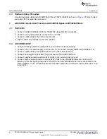
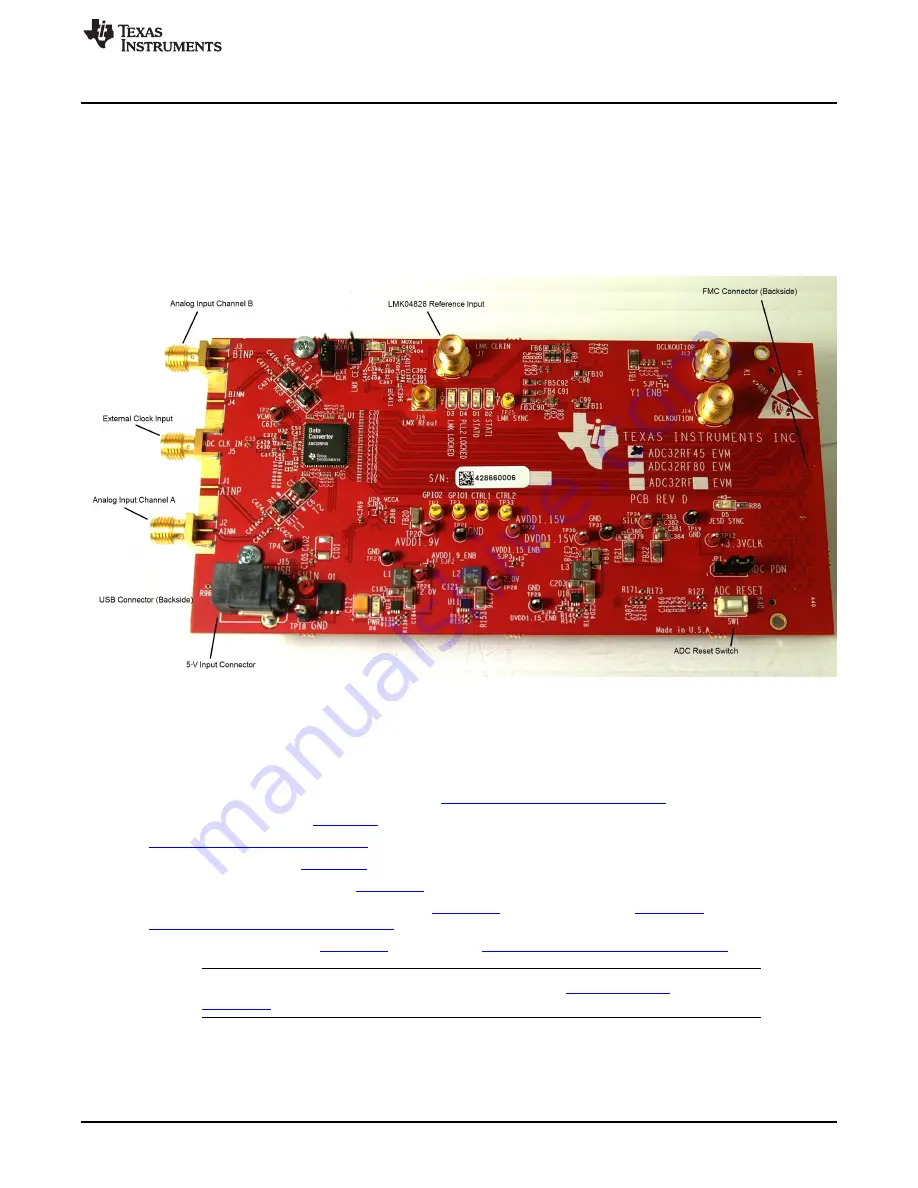
The EVM features are labeled in

Figure 1

.

Figure 1. EVM Feature Locations

1.4

References

Use the following links to available documentation and software:

ADC32RFxx EVM software, available from:

www.ti.com/tool/ADC32RFxxEVM

ADC32RF45 datasheet (

SBAS747

)

www.ti.com/product/ADC32RF45

LMK04828 datasheet (

SNAS605

)

TSW14J56EVM User’s Guide (

SLWU086

)

High Speed Data Converter Pro software (

SLWC107

) and User's Guide (

SLWU087

), available at

www.ti.com/tool/dataconverterpro-sw

HSDC Pro GUI Updates (

SLWC106

), available at

www.ti.com/tool/dataconverterpro-sw

NOTE:

The EVM schematics, layout, and BOM are available on the

ADC32RFxxEVM

tool page on

www.ti.com

.

Содержание ADC32RF45 EVM

Страница 1: ...e Setup Procedure 6 3 ADC32RFxx Quick Start Procedure ADC32RF45 Bypass LMFS82820 Mode 6 3 1 TSW14J56 6 3 2 ADC32RF4x EVM 6 3 3 High Speed Data Converter Pro HSDC Pro 12 4 ADC32RF80 Quick Start Procedure Digital DDC Block Decimation Plus NCO External Clocking 13 4 1 TSW14J56 13 4 2 ADC32RF80 EVM 13 4 3 High Speed Data Converter Pro HSDC Pro 18 5 ADC32RF4x RF80 Internally Generated Clocking 21 5 1 A...

Страница 2: ... output over a standard FPGA Mezzanine Card FMC interface connector The ADS54J45 EVM is designed to work seamlessly with TI s TSW14J56 EVM JESD204B data capture pattern generator card through the High Speed Data Converter Pro HSDC Pro software tool for high speed data converter evaluation The ADC32RF45 EVM is also designed to work with many of the development kits from leading FPGA vendors that co...

Страница 3: ...The EVM features are labeled in Figure 1 Figure 1 EVM Feature Locations 1 4 References Use the following links to available documentation and software ADC32RFxx EVM software available from www ti com tool ADC32RFxxEVM ADC32RF45 datasheet SBAS747 www ti com product ADC32RF45 LMK04828 datasheet SNAS605 TSW14J56EVM User s Guide SLWU086 High Speed Data Converter Pro software SLWC107 and User s Guide S...

Страница 4: ...ration to be closer to what the end application requires In this way the user can know that the hardware is functioning and that there is a working configuration that they can go back to in the event of difficulty developing their own configuration The HSDC Pro GUI that comes with the TSW14J56 requires initialization files for both the decimation and mixer logic called Digital Down Convert DDC tha...

Страница 5: ...ows XP If Windows XP does not automatically install the drivers follow the prompts on the screen to do so Do not let Windows XP search Microsoft Update for the drivers but do let Windows XP install the drivers automatically Windows 7 After installing the GUI Windows 7 should automatically be able to install the drivers for the ADC32RFxxEVM with no input from the user 2 2 2 High Speed Data Converte...

Страница 6: ...B connector J9 4 Flip the power switch SW6 to the ON position 3 2 ADC32RF4x EVM 1 Verify the clocking selection jumper JP3 is set to EXT for external clocking 2 Connect a 5 V 3 A power supply to connector J15 Do not use a supply that is rated less than 3 A 3 Connect a USB cable to the USB connector J11 bottom side of board 4 Connect an analog RF signal from the signal source to the AINP SMA J2 5 C...

Страница 7: ...94912 GHz 5 Sample Example This example captures data from channel A of the ADC32RF45 EVM sampling at 2 94912 GHz with a 1900 MHz input source This procedure uses a cfg file to set up the LMK04828 clock device first and then another cfg file to set up the ADC This is always the required sequence The ADC requires the device clock and SYSREF signals to be present before the ADC can be properly confi...

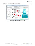
Страница 8: ...i com 8 SLAU620A April 2016 Revised May 2016 Submit Documentation Feedback Copyright 2016 Texas Instruments Incorporated ADC32RF45 RF80 EVM Quick Startup Guide Figure 3 ADC32RFxxEVM GUI LMK04828 PLL1 Page 4 Click on the Low Level View tab 5 Click on the Load Config icon ...

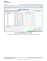
Страница 9: ...LAU620A April 2016 Revised May 2016 Submit Documentation Feedback Copyright 2016 Texas Instruments Incorporated ADC32RF45 RF80 EVM Quick Startup Guide Figure 4 ADC32RFxxEVM GUI Low Level Page 6 Navigate to the provided file called LMK_ADC32RF45_LMF_82820_ExtClock cfg and click OK ...

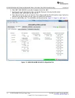
Страница 10: ...re 5 ADC and LMK Configuration Files 7 Press SW1 ADC RESET to provide a hardware reset to the ADC 8 Go to the Low Level View tab and click Load Config Navigate to the provided file called ADC32RF4x_12bit_LMFS_82820 cfg and press OK 9 Press Read All on the Low Level View tab The settings loaded by the ADC config file in step 7 will not be reflected in the ADC32RFxx main tab unless the Read All is p...

Страница 11: ...dure ADC32RF45 Bypass LMFS82820 Mode 11 SLAU620A April 2016 Revised May 2016 Submit Documentation Feedback Copyright 2016 Texas Instruments Incorporated ADC32RF45 RF80 EVM Quick Startup Guide Figure 6 ADC32RFxxEVM GUI ADC Configuration Tab ...

Страница 12: ...o v4 2 or newer by going to Start Menu All Programs Texas Instruments High Speed Data Converter Pro 2 Click OK to connect to the TSW14J56 If there is more than one TSW14J56 connected to the host PC select the appropriate serial number of the board to be programmed 3 Select the ADC tab at the top of the GUI 4 Use the Select ADC drop down menu at the top left corner to select ADC32RF45_LMF_82820 Fig...

Страница 13: ...lock Decimation Plus NCO External Clocking 4 1 TSW14J56 1 Connect the ADC32RF80 EVM to the TSW14J56 using the FMC connectors 2 Connect a 5 V power supply to connector J11 5V IN 3 Connect a USB cable to the USB connector J9 4 Flip the power switch SW6 to the ON position 4 2 ADC32RF80 EVM 1 Verify jumper JP3 is set for position EXT to select external clocking 2 Connect a 5 V 3 A power supply to conn...

Страница 14: ... setup the LMK04828 then the LMX2582 if the clock synthesizer is used and finally the ADC32RF80 The ADC requires the device clock and SYSREF signals to be present before the ADC can be properly configured so the LMK and optional LMX if used setup must have been done before configuring the ADC 1 Open the ADC32RFxx EVM RevD GUI 2 Verify that the green USB Status indicator is lit If it is not lit cli...

Страница 15: ...mation Plus NCO External Clocking 15 SLAU620A April 2016 Revised May 2016 Submit Documentation Feedback Copyright 2016 Texas Instruments Incorporated ADC32RF45 RF80 EVM Quick Startup Guide Figure 11 Low Level Page Figure 12 ADC32RF4x ADC32RF80 DDC Configuration Files ...

Страница 16: ...rovide a hardware reset to the ADC 7 Go to the Low Level View tab and click Load Config Navigate to the provided file called ADC32RF4x_DDC_8xIQ_8821 cfg and click OK 8 Press Read All on the Low Level View tab The settings loaded by the ADC cfg file in step7 will not be reflected in the ADC32RFxx main tab unless the Read All is performed 9 Go to the ADC32RFxx tab The ADC32RFxx tab should look like ...

Страница 17: ... DDC Block Decimation Plus NCO External Clocking 17 SLAU620A April 2016 Revised May 2016 Submit Documentation Feedback Copyright 2016 Texas Instruments Incorporated ADC32RF45 RF80 EVM Quick Startup Guide Figure 14 ADC32RFxxEVM GUI DDC Configuration Tab ...

Страница 18: ... NCOs in the ADC32RF80 are set to a desired LO frequency by a numeric control that is a fraction of the sampling frequency If the sampling frequency changes then the NCO frequency changes In order to find the input tone in the resulting FFT capture the sampling frequency and the NCO frequency must be known in order to know where the input tone should be located in the final FFT result 4 3 High Spe...

Страница 19: ...DC click Yes and wait for the firmware to download to the TSW14J56 The following message appears while the firmware is downloading to the FPGA Downloading firmware does not mean the GUI is looking for newer revisions at ti com It simply means the bitfile for the firmware for the FPGA is being pushed to the FPGA through the USB cable Figure 18 Download Firmware 6 After the firmware download has com...

Страница 20: ... Capture in HSDC Pro to capture data from the ADC 10 Select Complex FFT 11 The result should match the example capture in Figure 21 The input tone is seen to be near 60 MHz because the signal generator is set to 1 96 GHz while we set the NCO in the ADC to 1 90 GHz So the input tone is mixed down to 60 MHz If the signal generators for the analog input tone and the clocking are synchronized then HSD...

Страница 21: ...or used for the analog input then connect the 10 MHz sync signal from the signal generator to the LMK04828 reference input J7 2 The procedure for loading the configuration files is as previously described the LMK04828 is configured first followed by the LMX2582 followed by the ADC32RFxx There are individual cfg files for many of the common frequencies that the EVM may be asked to support all gener...

Страница 22: ...oading the configuration files is as previously described the LMK04828 is configured followed by the ADC32RFxx There are individual cfg files for many of the common frequencies that the EVM may be asked to support all generated from the 122 88 MHz VCXO installed on the EVM The configuration files used for the ADC32RF45 are slightly different than those for the ADC32RF80 and they are not interchang...

Страница 23: ...ring the warranty period to the address designated by TI and that are determined by TI not to conform to such warranty If TI elects to repair or replace such EVM TI shall have a reasonable time to repair such EVM or provide replacements Repaired EVMs shall be warranted for the remainder of the original warranty period Replaced EVMs shall be warranted for a new full ninety 90 day warranty period 3 ...

Страница 24: ... by Industry Canada to operate with the antenna types listed in the user guide with the maximum permissible gain and required antenna impedance for each antenna type indicated Antenna types not included in this list having a gain greater than the maximum gain indicated for that type are strictly prohibited for use with this device Concernant les EVMs avec antennes détachables Conformément à la rég...

Страница 25: ... connecting any load to the EVM output If there is uncertainty as to the load specification please contact a TI field representative During normal operation even with the inputs and outputs kept within the specified allowable ranges some circuit components may have elevated case temperatures These components include but are not limited to linear regulators switching transistors pass transistors cu...

Страница 26: ...F REMOVAL OR REINSTALLATION ANCILLARY COSTS TO THE PROCUREMENT OF SUBSTITUTE GOODS OR SERVICES RETESTING OUTSIDE COMPUTER TIME LABOR COSTS LOSS OF GOODWILL LOSS OF PROFITS LOSS OF SAVINGS LOSS OF USE LOSS OF DATA OR BUSINESS INTERRUPTION NO CLAIM SUIT OR ACTION SHALL BE BROUGHT AGAINST TI MORE THAN ONE YEAR AFTER THE RELATED CAUSE OF ACTION HAS OCCURRED 8 2 Specific Limitations IN NO EVENT SHALL T...

Страница 27: ...esponsible for compliance with all legal regulatory and safety related requirements concerning its products and any use of TI components in its applications notwithstanding any applications related information or support that may be provided by TI Buyer represents and agrees that it has all the necessary expertise to create and implement safeguards which anticipate dangerous consequences of failur...

Страница 28: ...Mouser Electronics Authorized Distributor Click to View Pricing Inventory Delivery Lifecycle Information Texas Instruments ADC32RF45EVM ADC32RF80EVM ...

Отзывы: