Tescom NEOLINE 1000 Скачать руководство пользователя страница 24

20 

                
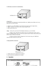
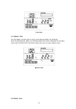
Connect the mains input to the UPS, press and hold the ON/OFF button for 1 second until 
the  buzzer  beeps.  At  this  point,  the  UPS  begins  to  conduct  self-diagnosis,  with  the 
load/battery capacity indicators on the front panel turned on and then off one after another. 
Seconds later, the UPS will begin to operate in Normal mode; meanwhile, the utility power 
indicator, inverter indicators will turn on. If the utility power is abnormal, the UPS will work 
in battery mode. 


2) 

Turning on without utility power:  
 
With no mains input fed to the UPS, hold and press the ON/OFF button for 1 second until 
the buzzer beeps. In the power on process, the UPS has the same operation as if it is 
connected to utility power except that the utility power indicator is not turned on and the 
battery indicator is turn instead. 
 

2.  Powering down the UPS 
 

The operation of powering down the UPS is shown as follow: 
 
1) 

Completely power down the UPS from Normal mode 
 
Hold and press the ON/OFF button persistently for more than 1 second to power off the 
UPS. If it is set up to work in bypass mode by WinPower software and the bypass 
indicator will be turn on to indicate that the UPS is working in bypass mode. In order to 
cut off the output from the UPS, simply cut off the utility power supply. Finally, not any 
display is shown on the front panel and no output is available from the UPS outlets. 
 

2) 

Completely power down the UPS from Battery mode 
 
Press the “ON/OFF” button persistently for more than 1 second to power off the UPS. 
When being powered off, the UPS will start self-diagnosis and all the load/battery 
capacity indicators will be turn on and off one after another. Finally, not any display is 
shown on the front panel and no voltage output is available from the UPS outlets. 

 
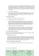
4.3.2  Conducting Battery self-diagnosis 


In UPS operation, users can manually initiate battery self-diagnosis to check the battery conditions. 
There are two methods to initiate the battery self-diagnosis: 
 
1.  Through the function button  


In normal mode, press and hold the function for more than 2 seconds until the buzzer beeps. 
At this point the indicators will blink cyclically, indicating the UPS has worked in battery mode 
and the battery self-diagnosis has started. The battery self-diagnosis will last for 10 seconds 
default (Users can set up it through WinPower software). In the event of a battery fault during 
battery self-diagnosis, the UPS will transfer to normal mode automatically. 
 

2.  Through the background monitoring software 


Users can also initiate battery self-diagnosis through the background monitoring software. 


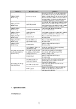
4.3.3  Error code and warming code 


Содержание NEOLINE 1000

Страница 1: ...1 NEOLINE SERIES 1000 2000 3000 1000XL 2000XL 3000XL 1 Phase In 1 Phase Out USER MANUAL...

Страница 2: ...2...

Страница 3: ...3 Thank you for purchasing product Observe the warnings on the machine and manual strictly and properly keep the manual Do not operate the UPS before read safety notes and operation instructions...

Страница 4: ...attery for Long backup Time UPS 11 3 3 3 Connecting Communication Interface 13 4 Operation 15 4 1 Introduction of Display Panel 15 4 2 Operation Mode 17 4 2 1 Normal mode 17 4 2 2 Bypass mode 18 4 2 3...

Страница 5: ...1...

Страница 6: ...ughly before operation the UPS and save this manual properly for future reference 2 Do not tear up or shatter the alarm table on the UPS and pay attention to it 3 Please do not overload the UPS beyond...

Страница 7: ...and other inlets 9 Do not store or use the device in the following environment Where there is inflammable gas corrosive agents or heavy dust Where the temperature is very high or low above 40 or below...

Страница 8: ...y AC power to connect strict load especially for the basic equipments in some areas as finance communication government traffic manufacture education and so on 2 1 System Type and Configuration There...

Страница 9: ...000XL UPS Figure 2 2 The Appearance of NEOLINE 2000XL UPS Computer Interface RS232 Intelligent Slot Surge Protection Output Breake Input External battery connector Computer Interface RS232 Intelligent...

Страница 10: ...of NEOLINE 3000XL UPS 2 3 Operating Principle Figure 2 4 The UPS operating principle Computer Interface RS232 Intelligent Slot Surge Protection Output Terminal Block Cover Terminal Block Breaker Input...

Страница 11: ...rough the DC DC converter 5 Bypass It is very important in the UPS system In the event of an UPS fault that will not lead to UPS shutdown the load will be automatically transferred to the bypass Meanw...

Страница 12: ...stallation Notes 1 When locating the UPS make sure there is no hazardous objects around the UPS and that the installation environment meets the specifications 2 The UPS should not be titled The air in...

Страница 13: ...following diagram Figure 3 1 Connection Method of Input for NEOLINE 1000 XL 3000 XL 1 Output cable connection Table 3 2 Output way of UPS Rating Model Quantity of output socket Output Terminal Block 1...

Страница 14: ...erminal block available for output as well The wring configuration is shown in the following diagram 1 Remove the small cover of the terminal block 2 Use AWG14 2 1mm 2 wires for wiring configuration 3...

Страница 15: ...1 First connect in series the batteries of the pack to ensure proper battery voltage Refer to Table 3 3 2 Take out the battery cable delivered with the UPS one end of the external battery cable is a p...

Страница 16: ...e UPS starts to charge the battery pack Figure 3 4 Battery connection diagram for Long Backup time models Note The length of the external battery cable is 2m If users need a longer one please consult...

Страница 17: ...nterface Computer interface The type of signals serial command RS232 is provided by the UPS to communicate with a host computer User can use WinPower software to monitor the UPS through the RS232 comm...

Страница 18: ...Note 1 Remove the cover board of the intelligent slot before any card is installed 2 Refer to some other relative documents for the use of the Winpower software and the AS400 and SNMP and CMC cards I...

Страница 19: ...ains power is normal the UPS System switches to Bypass mode by pressing OFF button and the inverter is off Select Button if the ups system is in bypass mode or self test mode the output frequency coul...

Страница 20: ...ronous it means current load is 50 When load 100 lighting and the OVER LOAD lighting with warning it means ups in overload Indicates ups input voltage value output voltage value output frequency value...

Страница 21: ...bout the utility power the battery the temperature and load could be displayed The operating mode code of the UPS is 03 If the UPS becomes overloaded the percentage of the load will be shown and the a...

Страница 22: ...ode is shown in the following diagram The information about the utility power the battery the UPS temperature and could be displayed The operating mode code of the UPS is 02 The UPS will beep once eve...

Страница 23: ...ode 4 3 Operating Instructions 4 3 1 Turning On and Completely Powering Down the UPS Note The battery is fully charged before delivery However storage and transportation will inevitably cause some cha...

Страница 24: ...utput from the UPS simply cut off the utility power supply Finally not any display is shown on the front panel and no output is available from the UPS outlets 2 Completely power down the UPS from Batt...

Страница 25: ...21 5 Maintenance 5 1 Battery Maintenance...

Страница 26: ...ed and discharged every 2 months Moreover the standard charging time should be not less than 12 hours 5 Batteries should not be replaced individually All batteries should be replaced at the same time...

Страница 27: ...er between the UPS operation modes Disconnect the main input to simulate a mains failure the UPS should transfer to battery mode and operate normally then recover the mains input the UPS should transf...

Страница 28: ...ult Please contact the distributor or Service center Display Fault 13 Buzzer long Fan of UPS is not connected or fault Please contact the distributor or Service center Display Fault 1 Buzzer long Inte...

Страница 29: ...of 46 Hz 54 Hz 2 The output frequency is 50Hz when the input frequency is not in the range of 46 Hz 54 Hz Battery mode 50 0 2 Hz Inverter overload capacity Utility power 25 108 5 Load 150 5 47s 25s 1...

Страница 30: ...Lower than 1000m Storage temperature 15 45 7 4 EMC Item Standard Level ESD IEC61000 4 2 LEVEL4 LEVEL4 RS IEC61000 4 3 LEVEL3 LEVEL3 EFT IEC61000 4 4 LEVEL4 LEVEL4 Surge IEC61000 4 5 LEVEL4 LEVEL4 7 5...

Страница 31: ...ranty The finished product of which the serial number is changed or lost Damage or loss resulted from force majeure or external causes Disassembly or modifications to the unit with no authorization Di...

Страница 32: ...28 AGKK10440 12 2012...

Отзывы: