

Einbau und Ausbau NITE-RF
Installation and Deinstallation NITE-RF
Einbau
1. Das Gerät und das Zubehör auspacken und auf Vollständigkeit überprüfen (siehe
„Lieferumfang“).
2. Die gelieferten Komponenten auf einwandfreien Zustand überprüfen.
3. Das Gerät angewinkelt mit obiger Nut des Hutschienenhalters [G] auf Hutschiene
hängen.
4. Das Gerät von oben nach unten auf die Hutschiene kippen, bis es einrastet.
Installation
1. Unpack the device and accessories and check for completeness (see "scope of delivery").
2. Check the delivered components for proper condition.
3. Put the product angled to the DIN rail and put the upper nut on the top of the DIN rail.
4. Push the device from top down to the DIN rail until the retainer locks on the DIN rail.
Ausbau
1. Das Gerät spannungsfrei schalten.
2. Die Spannungsklemme [F] vom Gerät lösen.
3. Alle Datenkabel vom Gerät lösen [D].
4. Die Hutschienenverrastung unter dem Gerät mit einem geeigneten Schraubendreher
nach unten bewegen.
5. Das Gerät von unten nach oben von der Hutschiene kippen.
6. Das Gerät von der Hutschiene nehmen.
Deinstallation
1. De-energize the device.
2. Disconnect the plug [F] from the Power supply jack of the device.
3. Disconnect all data cables from the device [D].
4. Unlock the retainer below the device with a suitable tool.
5. Flip the device from down to top from the DIN rail.
6. Remove the device from the DIN rail.
Einbau und Ausbau NITE-RW
Installation and Deinstallation NITE-RW
Einbau
1. Das Gerät und das Zubehör auspacken und auf Vollständigkeit überprüfen (siehe
„Lieferumfang“).
2. Die gelieferten Komponenten auf einwandfreien Zustand überprüfen.
3. M4 Löcher für die Wandmontage (siehe Skizze) vorbereiten. Auf jeder Seite mindestens 1
Loch zur Befestigung vorbereiten.
4. Die Lochabstände sind der Skizze zu entnehmen.
5. Das Gerät mit einer Linsenkopfschraube passend zum Untergrund mit Hilfe der
Seitenplatte [G] an der Wand befestigen.
6. Die Schraube mit einem Drehmoment von mindestens 2 Nm festziehen.
Installation
1. Unpack the device and accessories and check for completeness (see "scope of delivery").
2. Check the delivered components for proper condition.
3. Prepare M4 holes for wall mounting (see sketch). Prepare at least 1 hole on each side for
wall mounting.
4. The hole distances are shown in the sketch.
5. Fix the device at the wall using a panhead screw fitting to the ground using the side plate
[G].
6. Tighten the screw with a torque of at least 2 Nm.
Ausbau
1. Das Gerät spannungsfrei schalten.
2. Die Spannungsklemme [F] vom Gerät lösen.
3. Alle Datenkabel vom Gerät lösen [D].
4. Die Schrauben lösen und das Gerät von der Wand/Untergrund nehmen.
Deinstallation
1. De-energize the device.
2. Disconnect the plug [F] from the Power supply jack of the device.
3. Disconnect all data cables from the device [D].
4. Loosen the screws and remove the device from the wall/surface.
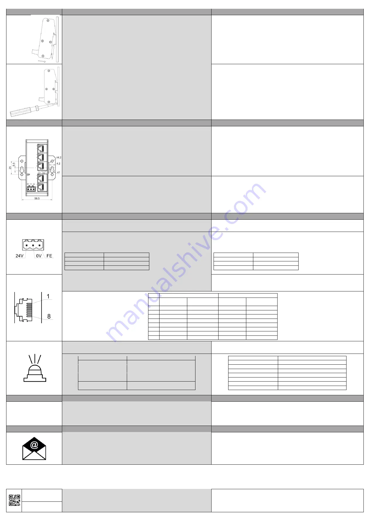
Elektrischer Anschluss
Electrical Interface
Nur Kupferleitungen mit zulässigem Temperaturbereich (-40 °C bis +80 °C) als
Anschlusskabel verwenden.
Only use copper cables with the valid temperature range (-40°C up to +80°C) as connection
cable.
Spannungsklemme
•
3-polig, steckbarer Schraubanschluss (+ - FE)
•
Anzugsmoment der Schrauben der Schraubklemmen 0,5...0,8 Nm (4,5...7 lbs-in)
•
Leiterquerschnitt 0,75 mm² ... 2,5 mm² (AWG 20 - 13)
Spannungsklemme
Belegung
Pol 1
24 VDC/VAC (50/60 Hz)
Pol 2
0 V
Pol 3
Funktionserde
Power supply plug
•
3-pole pluggable, screw connector (+ - FE)
•
Tightening torque of the screws of the power supply 0.5...0.8 Nm (4.5...7 lbs-in)
•
Wire diameter 0,75 mm² ... 2,5 mm² (AWG 20 - 13)
Power Supply Plug
Pinning
Pole 1
24 VDC/VAC (50/60 Hz)
Pole 2
0 V
Pole 3
Functional Earth
RJ45-Schnittstellen
•
Die Ethernet-Kabel mit RJ45-Stecker in beliebige RJ45-Schnittstellen [D] stecken.
•
Den RJ45-Stecker auf festen Sitz überprüfen.
RJ45-interfaces
•
Connect the Ethernet cables with RJ45-connectors to any RJ45-interfaces [D].
•
Proof the RJ45-plug for proper connection.
10 / 100 Base-T(X)
1000 Base-T
MDI
connection
MDI-X
connection
MDI
connection
MDI-X
connection
1
TX+
RX+
BI_DA+
BI_DB+
2
TX-
RX-
BI_DA-
BI_DB-
3
RX+
TX+
BI_DB+
BI_DA+
4
-
-
BI_DC+
BI_DD+
5
-
-
BI_DC-
BI_DD-
6
RX-
TX-
BI_DB-
BI_DA-
7
-
-
BI_DD+
BI_DC+
8
-
-
BI_DD-
BI_DC-
LED Status
•
Die Beschreibungen für [C] gelten nur für Full Gigabit Switches.
LED status
•
The descriptions for [C] are only valid for Full Gigabit Switches.
LED Status
Bemerkungen
LED [A] leuchtet grün
Versorgungsspannung liegt an
LED [B] aus
Kein Link
LED [B] leuchtet grün
Link aktiv 10/100 Mbit/s
LED [B] blinkt grün
Link aktiv & Datentransfer 10/100 Mbit/s
LED [C] aus
Kein Link
LED [C] leuchtet grün
Link aktiv 1000 Mbit/s
LED [C] blinkt grün
Link aktiv & Datentransfer 1000 Mbit/s
LED Status
Remarks
LED [A] lighted green
Power supply attached
LED [B] off
No Link established
LED [B] lighted green
Link active 10/100 Mbit/s
LED [B] blinking green
Link active & data transfer 10/100 Mbit/s
LED [C] off
No Link established
LED [C] lighted green
Link active 1000 Mbit/s
LED [C] blinking green
Link active & data transfer 1000 Mbit/s
Inbetriebnahme
Start-Up
1. Zunächst den korrekten / eingerasteten Sitz des Gerätes auf der Hutschiene prüfen.
2. Die Spannungsversorgung an der Spannungsversorgungsbuchse [E] anschließen.
3. Die Datenkabel an den RJ45-Schnittstellen [D] anschließen und auf korrekte Funktion
prüfen; hierzu die Tabelle „LED Status“ beachten.
4. Bei F
ehlfunktion bitte das Kapitel „Erste Hilfe bei Fehlfunktion“ beachten.
1. At first check, if the device is correctly mounted on the DIN rail.
2. Connect the power supply to the power supply jack [E].
3. Connect the data cables to the RJ45-interfaces [D] and check for correct function; refer to
the table "LED Status".
4. In case of malfunction, please refer to the chapter "First aid in case of malfunction".
Erste Hilfe
First aid
1. Den Spannungsanschluss überprüfen.
2. Die LED-Aktivität überprüfen
; siehe Tabelle „LED Status“.
3. Netzwerkkabel überprüfen: korrekter Sitz? Link aufgebaut? Eventuell durch Stecken auf
einen anderen Port den Fehler auf einen Port reduzieren.
4. Kabel tauschen, um ein fehlerhaftes Kabel auszuschließen.
5. Bei weiteren Fragen oder andauernder Fehlfunktion kontaktieren Sie bitte:
1. Check the nominal voltage connection.
2. Check the LED activity, refer to the table
“LED status”.
3. Check the data cables; Are they correctly fitted? Is there a link established? Try to activate
another port, to check if only one port has malfunction.
4. Change the cable, to be sure the cable has no malfunction.
5. For further questions or remaining malfunction, please contact: [email protected]
TERZ Industrial Electronics GmbH
Gewerbepark 5a
D-49143 Bissendorf, Germany
Tel. +49 5402 60 80 970
Fax +49 5402 60 80 979
Hinweis: Technische und inhaltliche Änderungen dieses Dokuments ohne Ankündigung sind vorbehalten. TERZ übernimmt keinerlei Verantwortung
oder Haftung für eventuelle Fehler oder Ungenauigkeiten in diesem Dokument. Alle Rechte an diesem Dokument und dessen Inhalte behalten wir uns
vor. Vervielfältigung, Verwendung des Inhalts oder die Bekanntgabe an Dritte in jedweder Form ist ohne schriftliche Genehmigung durch TERZ nicht
gestattet.
Copyright© 2020 TERZ Industrial Electronics GmbH. Alle Rechte vorbehalten.
Note: We reserve the right to make technical changes to this document without prior notice. TERZ assumes no responsibility or liability for any errors or
inaccuracies in this document. All rights to this document and its contents are reserved. Duplication, use of the content or announcement to third parties
in any form is not permitted without written permission from TERZ.
Copyright © 2020 TERZ Industrial Electronics GmbH. All rights reserved.
10012020
TZIM1X1X0XDEA
[email protected]
www.terz-ie.com


