6
Revision H
August 19, 1996
2.3.2
ANTENNAS
The three cardinal points for antenna installation are location, mounting and electrical
characteristics.
Antenna Location:
Provide an area where shadowing of the antenna will not occur (eg. blocking of the
signal by other parts of the aircraft). Remember that at VHF frequencies and above,
direct line of sight signals are required from ground stations to the antenna and for
maximum effective range. Consider that close proximity of an antenna to other
antennas or noise sources may create interference problems. Read carefully and
follow closely the recommendations of the antenna manufacturer about antenna
location.
Antenna Mounting:
Proper attachment of any antenna to the aircraft surface is of primary importance.
Carefully clean all paint and corrosion off the mounting surface and apply an anti-
corrosion treatment. Do the same to the inside surface if a backing or nut plate is to
be used. Mount the antenna securely per the antenna manufacturer’s
recommendations and check carefully to insure good electrical bonding. Do not
mount any antenna to doors, hatches, inspection plates or other moveable surfaces
because proper bonding to the aircraft surface cannot be accomplished. After proper
mounting and bonding is achieved, a bead of high quality RTV around the junction of
the antenna base and the aircraft surface will prevent water seepage and corrosion
from forming between the antenna base and aircraft surface.
Antenna Electrical Characteristics:
Use the antenna supplied with the avionics equipment, or if not supplied, the
antenna(s) recommended by the avionics manufacturer. If no specific antenna is
recommended, choose an antenna which provides good service for the frequency
range and the service conditions of the aircraft (eg. speed, altitude, etc.). If a signal
splitter is to be used, compare the specifications carefully to the application. Many
installation problems are encountered with improper application of signal splitters! If
in doubt, test the power and frequency characteristics of the splitter on the bench to
be sure.
Simple antenna problems such as shorting or open circuit problems can be determined
by use of an ohmmeter, although certain types of antennas may require use of ramp
test equipment to check radiation. But, by far, the most common antenna problems
are diagnosed to be coax or connectors, antenna bonding, or signal splitters. Never
allow an aircraft antenna to be painted.
Содержание TN 200D
Страница 16: ...12 Revision H August 19 1996 THIS PAGE INTENTIONALLY LEFT BLANK ...
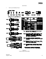
Страница 17: ...Revision H August 19 1996 13 SECTION III 3 INSTALLATION DRAWINGS Figure 3 1 Coax Connector Instructions ...
Страница 18: ...14 Revision H August 19 1996 THIS PAGE INTENTIONALLY LEFT BLANK ...
Страница 19: ...Revision H August 19 1996 15 Figure 3 2 Coax Connector Instructions ...
Страница 20: ...16 Revision H August 19 1996 THIS PAGE INTENTIONALLY LEFT BLANK ...
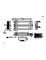
Страница 21: ...Revision H August 19 1996 17 18 Figure 3 3 TN 200D Outline Dimensions ...
Страница 22: ...Revision H August 19 1996 19 20 Figure 3 4 Typical Outline Drawing Dual Tray ...
Страница 23: ...Revision H August 19 1996 21 22 Figure 3 5 Outline Drawing 3 Option ...
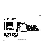
Страница 24: ...Revision H August 19 1996 23 24 Figure 3 6 Interconnect Drawing TN 200D Without Glideslope ...
Страница 25: ...Revision H August 19 1996 25 26 Figure 3 7 Interconnect Diagram TN 200D With Glideslope ...
Страница 33: ...34 Revision H August 19 1996 THIS PAGE INTENTIONALLY LEFT BLANK ...
Страница 35: ...36 Revision H August 19 1996 THIS PAGE INTENTIONALLY LEFT BLANK ...
Страница 37: ...38 Revision H August 19 1996 6 2 INSTALLATION NOTES ...


