15
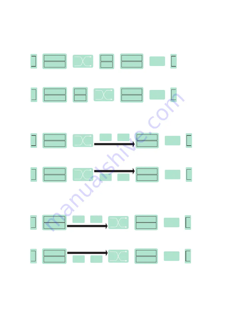
Figure 32. CAM configuration
SAT
INPUT
q
Demodulator 1
Demodulator 2
q
Up
converter
q
q
DVB-T
output
q
q
q
Modulator 1
Modulator 2
CAM position on output, individual CAM-s
q
q
q
q
CAM position on input, individual CAM-s
q
q
TS Multiplex
&
processing
SAT
INPUT
q
Demodulator 1
Demodulator 2
q
Up
converter
q
q
DVB-T
output
q
q
q
Modulator 1
Modulator 2
CAM 1
CAM 2
q
q
q
q
q
q
TS Multiplex
&
processing
CAM 1
CAM 2
SAT
INPUT
q
Demodulator 1
Demodulator 2
q
q
Up
converter
q
q
DVB-T
output
q
q
q
Modulator 1
Modulator 2
CAM position on output, CAM-s chained on Line1
q
q
q
TS Multiplex
&
processing
CAM 1
q
CAM 2
SAT
INPUT
q
Demodulator 1
Demodulator 2
q
q
Up
converter
q
q
DVB-T
output
q
q
q
Modulator 1
Modulator 2
CAM position on output, CAM-s chained on Line2
q
q
q
TS Multiplex
&
processing
CAM 1
q
CAM 2
SAT
INPUT
q
Demodulator 1
Demodulator 2
q
Up
converter
q
q
DVB-T
output
q
q
q
Modulator 1
Modulator 2
CAM position on input, CAM-s chained on Line1
TS Multiplex &
processing
q
q
CAM 1
q
CAM 2
CAM position on input, CAM-s chained on Line2
q
q
CAM 1
q
CAM 2
q
q
SAT
INPUT
q
Demodulator 1
Demodulator 2
q
Up
converter
q
q
DVB-T
output
q
q
q
Modulator 1
Modulator 2
TS Multiplex &
processing
q
q
Configuration settings and information about CA modules is split into different tabs. Most important table “Configuration of
CA modules” can be found in “CAM conf.” tab. In the "Configuration of CA modules" table CAM restart function in case of
descrambling error can be enabled. It is recommended to turn off this option if not activated conditional access card has been
inserted. “CAM settings” and “CAM position” parameters changes the flow of TS. Demod.1 and Demod.2 streams can be
descrambled separately by selecting “Invidual CAM-s” or “Сhained on the line 1” or 2 as shown in Figure 32. CAM position
can be changed from output to input.
For example
: “CAM position” is set to “on input” and “CAM settings” is set to “Chained on line #1”. This means that Demod.1
input’s stream travels through CAM 1 followed by CAM 2, then goes to multiplexer and finally to Modulator, see Figure 32.


