


9
4
7. Operating
7.1 Initial configuration
All modules leave the factory with this control Ethernet interface IP address: 192.168.1.10. In order to avoid conflicts with
other IP addresses, it is necessary to perform an initial configuration in local mode. Subsequently, it will be possible to access
the modules via the local area network (LAN), either to re-programme it or to check is operating status.
The modules leave the factory with the following Control Ethernet interface TCP/IP configuration:
IP address of the module
:
192.168.1.10
Subnet mask
:
255.255.255.0
Default Gateway
:
192.168.1.1
To access each module, use a PC or MAC personal computer equipped with an Ethernet
card and RJ-45 cable (CAT-5E or CAT-6). The IP address of the PC/MAC must be configured
within the following range: 192.168.1.2 - 192.168.1.254 (do not use 192.168.1.10, since this is
the IP address of the module to be configured). To start the configuration of the module, open
your web browser and type in the following direction: http://192.168.1.10. The login prompt
will appear on the screen (see Figure 6.). Module can be controlled using any web browser.
The exception is Internet Explorer, which must be 10.0 version or higher.
Figure 6. Login prompt
Access to the site is protected by user name and password. The default user name and password is
admin
. Enter the
user name and password and click on "
Login"
button.
Note
: the default password -
admin
- can (and must) be changed as explained on section
7.6.5
.
During initial configuration you need to change the default control and streaming Ethernet interfaces TCP/IP configuration
as explained on section
7.5
.
Control interface IP address reset to default procedure: press the "RESET" [7] button (Figure 1) for more than 3 seconds and
release it. After this operation the control interface IP address will be set to
192.168.1.10
, user name and password set to
admin
.
7.2 General configuration
Initial program screen
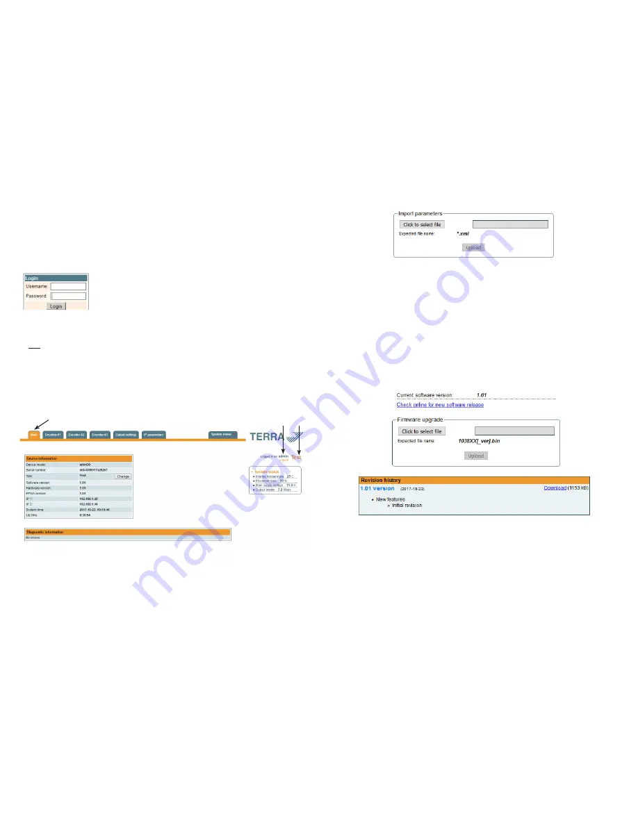
The first screen that appears when the module accessed contains the "Main" window, which gives general information
on the device.
Figure 7. General information screen
In the top of each configuration screen you will see a main menu tabs [1].
Using it, you can switch between the different configuration menus. The tab highlighted in yellow shows which menu is
active at a given moment. The "System menu" tab contains several submenu.
Also common elements for all screens is module title [2] and login information strings [3]. The module title can be changed
after pressing the "Change" button in the "Device information" table. Pressing on the "Logout" string you can logout from
module control.
[1]
[2]
[3]
Figure 14. Import parameters
Press “Upload” button to send the file to the device. It will take several seconds to update all parameters after file upload.
After that, device will function with new configuration. No restart is required.
7.6.4. Firmware upgrade
Device firmware can be upgraded via web browser. Press the “Click to select file” button and select firmware binary file. If
valid file was selected, a version number of new firmware will be displayed. Otherwise an error message will appear. Press
the “Upload” button to upload new firmware to the device. Upload progress bar will appear and may take several seconds
to upload, depending on the size of a file and a network connection speed. A message will be displayed asking to restart
the device when the file was sent to the device. New firmware will be programmed into the device only after restart. It may
take additional minute or more to flash new program. Device will start up with a new firmware and continue to operate with
previous parameters. Additional new firmware features (if any) may need to setup additionally to take effect.
Avoid power supply interruption when a programming process is going on.
Device has possibility to load software revision history and check availability for new software release. Click the “Check
online” link. If computer (not device!) has internet access, it will show a list of all software releases with links to binary files.
Binary file can be downloaded and saved to computer (see Figure 15 "Firmware upgrade"). After that, use the firmware
upgrade method as described above.
Figure 15. Firmware upgrade
7.6.5. User management
User may change a password here. Length of the password is up to 16 symbols. Type current password and double enter
new password to change it.
If logged in user has admin role, new users can be added (see Figure 16 "User management").


