


DS_1209F_004
73S1209F Data Sheet
Rev. 1.2
41
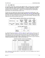
Miscellaneous Control Register 0 (MISCtl0): 0xFFF1
Å
0x00
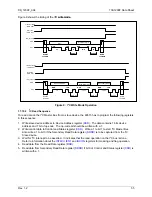
Transmit and receive (TX and RX) pin selection and loop back test configuration are set up via this register.
Table 37: The MISCtl0 Register
MSB LSB
PWRDN
– – – – –
SLPBK
SSEL
Bit Symbol
Function
MISCtl0.7
PWRDN
This bit places the 73S1209F into a power down state.
MISCtl0.6 –
MISCtl0.5 –
MISCtl0.4 –
MISCtl0.3 –
MISCtl0.2 –
MISCtl0.1 SLPBK
1 = UART loop back testing mode. The pins TXD and RXD are to be
connected together externally (with SLPBK =1) and therefore:
SLPBK SSEL
Mode
0 0 normal
using
Serial_0
0 1 normal
using
Serial_1
1
0
Serial_0 TX feeds Serial_1 RX
1
1
Serial_1 TX feeds Serial_0 RX
MISCtl0.0 SSEL
Selects either Serial_1 if set =1 or Serial_0 if set = 0 to be connected
to RXD and TXD pins.
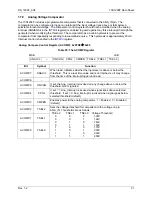
1.7.4.1 Serial
Interface
0
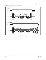
The Serial Interface 0 can operate in four modes:
•
Mode 0
Pin RX serves as
input
and output. TX outputs the shift clock. Eight bits are transmitted with the LSB
first. The baud rate is fixed at 1/12 of the crystal frequency. Reception is initialized in Mode 0 by
setting the flags in
as follows: RI0 = 0 and REN0 = 1. In other modes, a start bit when REN0
= 1 starts receiving serial data.
•
Mode 1
Pin RX serves as input, and TX serves as serial output. No external shift clock is used, 10 bits are
transmitted: a start bit (always 0), 8 data bits (LSB first), and a stop bit (always 1). On receive, a start
bit synchronizes the transmission, 8 data bits are available by reading
, and stop bit sets the
flag RB80 in the Special Function Register
. In mode 1 either internal baud rate generator or
timer 1 can be use to specify baud rate.
•
Mode 2
This mode is similar to Mode 1, with two differences. The baud rate is fixed at 1/32 or 1/64 of
oscillator frequency and 11 bits are transmitted or received: a start bit (0), 8 data bits (LSB first), a
programmable 9th bit, and a stop bit (1). The 9th bit can be used to control the parity of the serial
interface: at transmission, bit TB80 in
is output as the 9th bit, and at receive, the 9th bit
affects RB80 in Special Function Register
.
•
Mode 3
The only difference between Mode 2 and Mode 3 is that in Mode 3 either internal baud rate generator
or timer 1 can be use to specify baud rate.
register is used to read/write data to/from the serial 0 interface.


