UM_1966B_024
73M1966B Evaluation Kit User Manual
Rev. 1.0
15
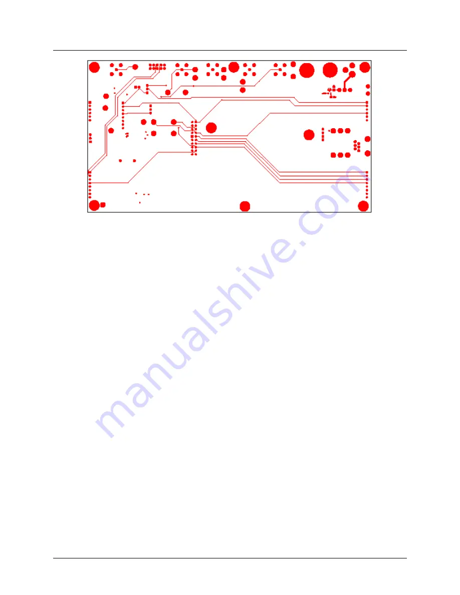
Figure 8: Motherboard: Bottom Layer
Страница 1: ...Simplifying System IntegrationTM 73M1966B Evaluation Kit User Manual March 19 2009 Rev 1 0 UM_1966B_024...
Страница 2: ...ny s warranty detailed in the Teridian Semiconductor Corporation standard Terms and Conditions The company assumes no responsibility for any errors which may appear in this document reserves the right...
Страница 3: ...3 Connecting to a Central Office Line Simulator 8 2 3 1 Considerations When Connecting to the Telephone Network 9 2 4 Graphical User Interface 9 2 5 Connecting the Power Supply 10 2 6 Applying Power...
Страница 4: ...e 3 Central Office Line Simulator 8 Figure 4 Simple DC Feed Circuit 9 Figure 5 73M1966 Motherboard Schematics 13 Figure 6 Motherboard Silk Screen Top 14 Figure 7 Motherboard Top Layer 14 Figure 8 Moth...
Страница 5: ...computer and to read its status conditions The kit demonstrates functionality and allows evaluation of the 73M1966B performance characteristics via the PCM channel measuring set which provides a sourc...
Страница 6: ...it includes A 73M1966 Demo Motherboard Rev D 73M1966B Demo Board D1966P11A Rev D3 A GUI parallel interface cable An AC to DC transformer wall plug A CD containing the GUI software and the documentatio...
Страница 7: ...he Power Supply Applying Power Figure 2 shows the basic connections of the 73M1966 Demo Motherboard and external equipment Be sure to connect the test set equipment and telephone network simulator bef...
Страница 8: ...the documentation for the test set being used for details about requirements and limits 2 2 Connecting the SPI to the PC Using the supplied parallel interface cable 1 Connect the 10 pin female end to...
Страница 9: ...stance will appear to the PCM 4 as an additional load in parallel with the impedance of the 73M1966B termination impedance so the measurements will not be accurate 2 3 1 Considerations When Connecting...
Страница 10: ...rd Use the supplied wall transformer that plugs directly into the board at J5 Do not use in conjunction with J1 and J2 Feed the board with 3 3 V and GND through the J1 and J2 connectors Cables are not...
Страница 11: ...ly which is down regulated on the Motherboard to 3 3 V Use either J5 or J1 and J2 but not both J6 PCM Highway Header connector to the PCM Highway J24 CLKO BNC connector for the clock output J30 RJ 11...
Страница 12: ...tested RXG1 0 RX boost TX RX Gain versus Frequency Tests the gain variation versus frequency across the audio band Shows the passband ripple and adherence to the frequency response template TX RX Gain...
Страница 13: ...2 3 4 5 6 R49 20K TP31 CALL PROG 1 J42 HEADER5X2 1 2 3 4 5 6 7 8 9 10 R46 120K LS1 INTERVOX AT 2308 J4 FROM MASTER 1 2 3 4 5 6 7 8 C27 1uF J6 PCM HIWAY INTERFACE 1 2 3 4 5 6 7 8 TP8 GND 1 RIGHT SIDE...
Страница 14: ...UM_1x66B_024 73M1966B Evaluation Kit User Manual Rev 1 0 14 5 2 PCB Layouts Figure 6 Motherboard Silk Screen Top Figure 7 Motherboard Top Layer...
Страница 15: ...UM_1966B_024 73M1966B Evaluation Kit User Manual Rev 1 0 15 Figure 8 Motherboard Bottom Layer...
Страница 16: ...J42 HEADER Sullins PBC36DAAN 1 J57 HEADER Sullins PBC36SAAN 1 LS1 Speaker Projects Unlimited AST 02308MR R 1 R28 100K Panasonic ERJ 3GEYJ104V 1 R29 1K Panasonic ERJ 3GEYJ102V 1 R46 120K Panasonic ERJ...
Страница 17: ...d Documentation The following 73M1x66B documents are available from Teridian Semiconductor Corporation 73M1866B 73M1966B Data Sheet 73M1966B Demo Board User Manual 73M1866B 73M1966B GUI User Guide 73M...
Страница 18: ...73M1966B Evaluation Kit User Manual UM_1966B_024 18 Rev 1 0 Revision History Revision Date Description 1 0 3 19 2009 First publication...
Страница 19: ...Mouser Electronics Authorized Distributor Click to View Pricing Inventory Delivery Lifecycle Information Maxim Integrated 73M1966B EVM...