background image

Third Edition • First Printing


Operator's Manual


Controls 


Part No. 1315875GT


Z

®

-40N • Z

®

-40N RJ 

29 


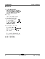
9  Auxiliary power switch 

Use auxiliary power if the primary power 

source (engine) fails. 

Simultaneously hold the auxiliary power switch 

to either side and activate the desired function. 

10  Red Emergency Stop button 

Push in the red Emergency Stop button to the 

off position to stop all functions and turn the 

engine off. Pull out the red Emergency Stop 

button to the on position to operate the 

machine. 

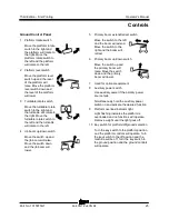
11  Proportional control handle for drive function 

and thumb rocker for steer function 
Move the control handle in the direction 

indicated by the blue arrow on the control 

panel and the machine will drive forward. 

Move the control handle in the direction 

indicated by the yellow arrow and the machine 

will drive backwards. 
Press the left side of the thumb rocker and the 

machine will steer to the left. Press the right 

side of the thumb rocker and the machine will 

steer to the right. 

12  Drive enable switch 

To drive when the drive enable LCD symbol is 

on, hold the drive enable switch to either side 

and slowly move the drive control handle off 

center. Be aware that the machine may move 

in the opposite direction that the drive and 

steer controls are moved. 

13  Inverter switch (if equipped) 

Move the inverter switch up to activate the 

inverter. Move the switch down to turn off the 

inverter. 

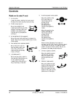
14  LCD readout screen 


1


see operator's manual 

2


contact maintenance 

3


hazard 

4


drive enable 

5


machine not level 

6


platform overload 

15  Thumb rocker switch for primary boom 

extend/retract function 

Press the bottom of the 

thumb rocker switch to 

extend the primary boom. 

Press the top of the thumb 

rocker switch to retract the 

primary boom. 


16  Dual axis proportional control handle for 

primary boom up/down and turntable rotate 

left/right functions 

Move the control handle up 

and the primary boom will 

raise. Move the control 

handle down and the 

primary boom will lower. 


Move the control handle to 

the right and the turntable 

will rotate to the right. Move 

the control handle to the left 

and the turntable will rotate 

to the left. 


1

2

3

4

5

6

Содержание Genie Z-40N

Страница 1: ...rator s Manual Serial Number Range Z 40N ANSI CSA North America South America Asia Z 40N RJ with Maintenance Information Original Instructions Third Edition First Printing Part No 1315875GT from Z40NF 6900 ...

Страница 2: ...15 Work Area Safety 16 Legend 23 Controls 24 Inspections 30 Operating Instructions 44 Transport and Lifting Instructions 51 Maintenance 54 Specifications 56 Copyright 2006 Terex Corporation Third Edition First Printing September 2022 Genie and Z are registered trademarks of Terex South Dakota Inc in the U S A and many other countries These machines comply with ANSI SAIA A92 20 CAN CSA B354 6 ...

Страница 3: ...ssis Serial label located under cover Intended Use and Familiarization Guide The intended use of this machine is to lift personnel including tools and materials to an aerial work site Before operating the machine it s the operator s responsibility to read and understand this familiarization guide Each person must be trained to operate a Mobile Elevating Work Platform MEWP Familiarization with the ...

Страница 4: ...0N RJ Part No 1315875GT Platform controls symbology and related machine movement Platform level Platform rotate Jib boom up down Jib boom rotate Primary boom up down Turntable rotate Primary boom extend retract Secondary boom up down Drive forward reverse Steer right left ...

Страница 5: ...ondary boom up down Sequential functions and movement Drive and steer Interlocked functions Elevated drive speed Elevated drive in an off level condition Drive enable when the boom is rotated past the non steer wheels All platform and ground controls Limitations of use The intended use of this machine is to lift personnel including tools and materials to an aerial work site Do not elevate the plat...

Страница 6: ...e action indicated in a respective bulletin To view any open bulletins for your machine visit us on the web at www genielift com Contacting the Manufacturer At times it may be necessary to contact Genie When you do be ready to supply the model number and serial number of your machine along with your name and contact information At minimum Genie should be contacted for Accident reporting Questions ...

Страница 7: ... worksite regulations You read understand and obey all applicable governmental regulations You are properly trained to safely operate the machine Safety Sign Maintenance Replace any missing or damaged safety signs Keep operator safety in mind at all times Use mild soap and water to clean safety signs Do not use solvent based cleaners because they may damage the safety sign material Hazard Classifi...

Страница 8: ...finiti ons Fire hazard Explosion hazard Explosion hazard Do not use ether or other high energy starting aids on machines equipped with glow plugs No smoking No flame Stop engine Fire extinguisher No smoking Explosion hazard Electrocution hazard Maintain required clearance Tip over hazard Tip over hazard Tip over hazard Tip over hazard Tire specifications ...

Страница 9: ...RJ 7 Wheel load Wind speed Maximum capacity Manual force Support the platform or boom during maintenance Tie down point Lifting point Platform tie down instructions Lifting and tie down instructions Lanyard anchorage points Corrosive acid Color coded direction arrows Runaway hazard Collision hazard Overhead obstruction ...

Страница 10: ...ing for power to platform Pressure rating for air line to platform Recovery procedure if tilt alarm sounds while elevated Platform uphill 1 Lower primary 2 Lower secondary 3 Retract primary Platform downhill 1 Retract primary 2 Lower secondary 3 Lower primary Read the operator s manual Access by trained and authorized personnel only Read the service manual Auxiliary lowering Crush hazard ...

Страница 11: ...Third Edition First Printing Operator s Manual General Safety Part No 1315875GT Z 40N Z 40N RJ 9 Gener al Safety ...

Страница 12: ...Operator s Manual Third Edition First Printing General Safety 10 Z 40N Z 40N RJ Part No 1315875GT ...

Страница 13: ...Third Edition First Printing Operator s Manual General Safety Part No 1315875GT Z 40N Z 40N RJ 11 ...

Страница 14: ...Operator s Manual Third Edition First Printing General Safety 12 Z 40N Z 40N RJ Part No 1315875GT ...

Страница 15: ...Third Edition First Printing Operator s Manual General Safety Part No 1315875GT Z 40N Z 40N RJ 13 ...

Страница 16: ...Operator s Manual Third Edition First Printing General Safety 14 Z 40N Z 40N RJ Part No 1315875GT ...

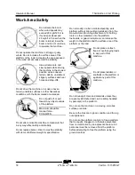
Страница 17: ...ine Occupants must wear a safety belt or harness in accordance with governmental regulations Attach the lanyard to the anchor provided in the platform Operators must comply with employer job site and governmental rules regarding the use of personal protective equipment All PFPE must comply with applicable governmental regulations and must be inspected and used in accordance with the PFPE manufactu...

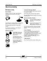
Страница 18: ...nds Keep away from the machine if it contacts energized power lines Personnel on the ground or in the platform must not touch or operate the machine until energized power lines are shut off Do not operate the machine during lightning or storms Do not use the machine as a ground for welding Tip over Hazards Occupants equipment and materials shall not exceed the maximum platform capacity Maximum pla...

Страница 19: ...face before raising the platform If the tilt alarm sounds when the platform is raised use extreme caution The Machine Not Level indicator light will come on and the drive function in one or both directions will not operate Identify the condition of the boom on the slope as shown below Follow the steps to lower the boom before moving to a firm level surface Do not rotate the boom while lowering If ...

Страница 20: ... that in any way affect safety and stability Do not replace items critical to machine stability with items of different weight or specification Do not modify or alter a mobile elevating work platform without prior written permission from the manufacturer Mounting attachments for holding tools or other materials onto the platform toeboards or guard rail system can increase the weight in the platfor...

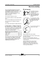
Страница 21: ...d position Platform downhill 30 17 Platform uphill 20 11 Side slope 25 14 Note Slope rating is subject to ground conditions with one person in the platform and adequate traction Additional platform weight may reduce slope rating See Driving on a Slope in the Operating Instructions section Fall Hazards Occupants must wear a safety belt or harness in accordance with governmental regulations Attach t...

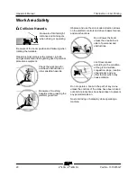
Страница 22: ... Be aware of crushing hazards when grasping the platform guard rail Observe and use the color coded direction arrows on the platform controls and drive chassis for drive and steer functions Do not lower the boom unless the area below is clear of personnel and obstructions Limit travel speed according to the condition of the ground surface congestion slope location of personnel and any other factor...

Страница 23: ...of the contact alarm assembly will reduce the rated platform capacity and must be subtracted from the total platform load The contact alarm assembly weighs 10 lbs 4 5 kg Be sure the contact alarm is securely installed Damaged Machine Hazards Do not use a damaged or malfunctioning machine Conduct a thorough pre operation inspection of the machine and test all functions before each work shift Immedi...

Страница 24: ...lamps with tools that may cause sparks Component Damage Hazard Do not use any battery charger greater than 48V to charge the batteries Both battery packs must be charged together Disconnect the battery pack plug before removing the battery pack Electrocution Burn Hazards Connect the battery charger to a grounded AC 3 wire electrical outlet only Inspect daily for damaged cords cables and wires Repl...

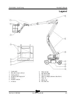
Страница 25: ...0N RJ 23 Legend 1 Foot switch 2 Manual storage container 3 Sliding mid rail 4 Lanyard anchorage points 5 Platform 6 Platform controls 7 Jib boom 8 Primary boom 9 Secondary boom 10 Ground controls 11 Power to charger between steer tires 12 Steer tire 13 Battery box 14 Non steer tire ...

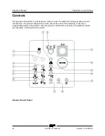
Страница 26: ...o be used as a means to raise the platform for storage purposes and for function tests The ground control station can be used in the event of an emergency to rescue an incapacitated person in the platform When the ground control station is selected the platform controls are inoperable including the E stop switch Ground Control Panel ...

Страница 27: ...se Move the switch down and the jib boom will lower 5 Primary boom extend retract switch Move the switch to the left and the boom will extend Move the switch to the right and the boom will retract 6 Primary boom up down switch Move the switch up and the primary boom will raise Move the switch down and the primary boom will lower 7 Used for optional equipment 8 Auxiliary power switch Use auxiliary ...

Страница 28: ...rs the machine has operated 13 Z 40 23N RJ Jib rotate switch Move the jib rotate switch to the right and the jib will move to the right Move the jib rotate switch to the left and the jib will move to the left 14 Secondary boom up down switch Move the switch up and the secondary boom will raise Move the switch down and the secondary boom will lower 15 Function enable switch Move the function enable...

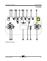
Страница 29: ...Third Edition First Printing Operator s Manual Controls Part No 1315875GT Z 40N Z 40N RJ 27 Platform Control Panel STOP 1 2 4 5 3 7 8 9 10 11 12 14 16 15 13 6 ...

Страница 30: ...ight and the jib will move to the right Move the jib rotate switch to the left and the jib will move to the left 6 Function speed control switch Move the switch to the left to decrease the function speeds for primary boom extend retract secondary boom up down and platform rotate Move the switch to the right to increase the function speeds for primary boom extend retract secondary boom up down and ...

Страница 31: ...eer to the right 12 Drive enable switch To drive when the drive enable LCD symbol is on hold the drive enable switch to either side and slowly move the drive control handle off center Be aware that the machine may move in the opposite direction that the drive and steer controls are moved 13 Inverter switch if equipped Move the inverter switch up to activate the inverter Move the switch down to tur...

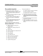
Страница 32: ...tion is designed to discover if anything is apparently wrong with a machine before the operator performs the function tests The pre operation inspection also serves to determine if routine maintenance procedures are required Only routine maintenance items specified in this manual may be performed by the operator Refer to the list on the next page and check each of the items If damage or any unauth...

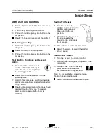
Страница 33: ...sing parts and unauthorized modifications Electrical components wiring and electrical cables Hydraulic hoses fittings cylinders and manifolds Hydraulic tank Drive and turntable motors and drive hubs Boom wear pads Tires and wheels Limit switches and horn Alarms and beacons if equipped Nuts bolts and other fasteners Platform entry mid rail or gate Lanyard anchorage points Check entire machine for C...

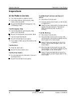
Страница 34: ... use the machine as it was intended Function Test Fundamentals The function tests are designed to discover any malfunctions before the machine is put into service The operator must follow the step by step instructions to test all machine functions A malfunctioning machine must never be used If malfunctions are discovered the machine must be tagged and removed from service Repairs to the machine ma...

Страница 35: ...operate 7 Hold the function enable switch to either side and activate each boom and platform function toggle switch Result All boom and platform functions should operate through a full cycle The descent alarm should sound while the boom is lowering Test the Tilt Sensor 8 Turn the key switch to platform control Pull out the platform red Emergency Stop button to the on position 9 Open the turntable ...

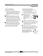
Страница 36: ... foot switch Test each machine function Result No functions should operate Test Machine Functions and Descent Alarm 21 Press down the foot switch 22 Activate each machine function control handle or toggle switch Result All boom and platform functions should operate through a full cycle The descent alarm should sound while the boom is lowering Test the Steering 23 Press down the foot switch 24 Pres...

Страница 37: ...rive chassis then come to an abrupt stop Note The brakes must be able to hold the machine on any slope it is able to climb Test the Drive Enable System 29 Press down the foot switch and lower the boom to the stowed position 30 Rotate the turntable until the primary boom moves past one of the non steer wheels Result The drive enable LCD symbol should come on and remain on while the boom is anywhere...

Страница 38: ...om If the drive speed with the primary or secondary boom raised or the primary boom extended exceeds 1 ft 30 cm per second immediately tag and remove the machine from service Test Drive Tilt Cutout 43 Press down the foot switch 44 With the boom fully stowed drive the machine onto a slope where the chassis pitch angle is greater than 4 5 Result The machine should continue to drive 45 Return to leve...

Страница 39: ... The machine should stop once the machine reaches 4 5 of chassis tilt and the alarm should sound at the platform controls 58 Lower the primary boom to the stowed position or drive in the opposite direction Result The machine should drive 59 Return to level ground and extend the primary boom approximately 1 6 ft 0 5 m 60 Drive the machine onto a slope where the chassis roll angle is greater than 4 ...

Страница 40: ...rm cable to release the actuator from the switch socket Result The contact alarm lights will flash and the machine horn will sound 71 Operate each machine function Result All machine functions should not operate 72 Insert the actuator into the switch socket Result The lights and horn will turn off 73 Operate each machine function Result All machine functions should operate a actuator b contact ala...

Страница 41: ...perator determine if the workplace is suitable for safe machine operation It should be performed by the operator prior to moving the machine to the workplace It is the operator s responsibility to read and remember the workplace hazards then watch for and avoid them while moving setting up and operating the machine Workplace Inspection Checklist Be aware of and avoid the following hazardous situat...

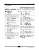
Страница 42: ...wer Mid rail 1 114117 Notice Battery Connection Diagram 2 114132 Ground Control Panel 1 Part No Decal Description Qty 114180 Label Wheel Load 4 114343 Label Emergency Lowering 1 114350 Label AC Inverter Power option 2 114390 Danger Electrocution Hazard 3 114397 Danger Tilt Alarm 1 133286 Label Power to Charger 1 218550 Danger Tip over Hazard 500 lbs 227 kg 1 218559 Danger Warning Tip over Crush Ha...

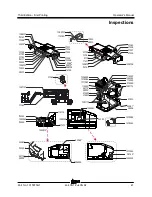
Страница 43: ...87 31785 114117 31788 31787 31785 114117 28372 72833 114180 1299757 27206 27207 27205 1299756 114180 1299757 31060 Ground control box 1316086 1256899 1317063 82366 1272242 38149 1293324 1256898 44981 114350 28174 28235 1280819 1278542 114390 114132 1278982 1294398 227213 114343 1263543 114390 31060 1267121 28236 44981 97815 1281174 114390 1262342 114397 1281174 218550 219487 114350 28174 28235 310...

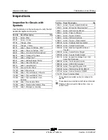
Страница 44: ... 1 114334 Label Electrocution Hazard Plug 1 114343 Label Emergency Lowering 1 Part No Decal Description Qty 114345 Label Tip over Hazard Batteries 2 114350 Label AC Inverter Power option 2 133067 Label Electrocution Hazard 3 133286 Label Power to Charger 1 219954 Label Tip over Hazard 1 219956 Label Platform Overload 1 219958 Label Tip over Crush Hazard 1 1262343 Label Runaway Machine Hazard 1 126...

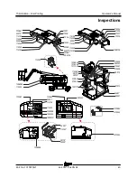
Страница 45: ...27204 114334 133286 52475 72086 114180 114249 82481 114345 114249 114180 27206 27207 27205 114252 1299756 114252 1286362 114252 133067 82487 114132 114343 1263542 1294398 1280819 44981 114350 28174 28235 1256898 133067 1263542 1272242 1281174 1316086 1256899 1278982 1278542 1281174 219958 133067 1262343 114248 97815 44981 82487 1317063 219954 114350 28174 28235 219956 ...

Страница 46: ...is the operator s responsibility to follow all the safety rules and instructions in the operator s safety and responsibilities manuals Using the machine for anything other than lifting personnel along with their tools and materials to an aerial work site is unsafe and dangerous Only trained and authorized personnel should be permitted to operate a machine If more than one operator is expected to u...

Страница 47: ...ce fails 1 Turn the key switch to ground or platform control 2 Pull out the red Emergency Stop button to the on position 3 Press down the foot switch when operating the auxiliary controls from the platform 4 Simultaneously hold the auxiliary power switch on and activate the desired function The drive function will not operate with auxiliary power Operation from Ground 1 Turn the key switch to grou...

Страница 48: ...control handle toward center Stop Return the control handle to center or release the foot switch Use the color coded direction arrows on the platform controls and the drive chassis to identify the direction the machine will travel Machine travel speed is restricted when the booms are raised or extended Drive Enable LCD symbol on indicates that the boom has moved just past either non steer wheel an...

Страница 49: ...ns are disabled Follow the Boom lowering procedure see Operating Instructions to restore drive function When the machine is stowed on a slope and the tilt alarm sounds the following functions are affected lift functions are disabled Return the machine to level ground to restore lift functions Machine Not Level LCD Symbol LCD Symbol on indicates the machine is not level The tilt alarm will be sound...

Страница 50: ... machine on incline symbol To determine the slope grade Measure the slope with a digital inclinometer OR use the following procedure You will need carpenter s level straight piece of wood at least 3 feet 1 m long tape measure Lay the piece of wood on the slope At the downhill end lay the level on the top edge of the piece of wood and lift the end until the piece of wood is level While holding the ...

Страница 51: ...hing warning lights When the contact alarm cable is tripped the lift and drive functions are disabled at the platform The audio and visual warnings will activate alerting others that assistance may be needed These notifications will continue until the system is reset 1 The contact alarm cable is tripped releasing the actuator from the switch socket 2 Insert the actuator into the switch socket to t...

Страница 52: ...l If necessary add only enough distilled water to cover the plates Do not overfill prior to the charge cycle 2 Replace the battery vent caps 3 Connect the battery charger to a grounded AC circuit 4 The charger will indicate when the battery is fully charged 5 Check the battery acid level when the charging cycle is complete Replenish with distilled water to the bottom of the fill tube Do not overfi...

Страница 53: ...e the vehicle capacity loading surfaces and chains or straps are sufficient to withstand the machine weight Genie lifts are very heavy relative to their size See the serial label for the machine weight See the inspections section for the serial label location Be sure the turntable is secured with the turntable rotation lock before transporting Be sure to unlock the turntable for operation Do not d...

Страница 54: ... the off position and remove the key before transporting Inspect the entire machine for loose or unsecured items Securing the Chassis Use chains of ample load capacity Use a minimum of 4 chains or straps Adjust the rigging to prevent damage to the chains Securing the Platform Make sure the jib and platform are in the stowed position Place a block under the edge of the platform beneath the platform...

Страница 55: ...r lines are sufficient to withstand the machine weight See the serial label for the machine weight Lifting Instructions Remove all loose items on the machine Use the turntable rotation lock to secure the turntable Determine the center of gravity of your machine using the table and the picture on this page Attach the rigging only to the designated lifting points on the machine There are four liftin...

Страница 56: ...ons When one or more of the symbols appear at the beginning of a maintenance procedure it conveys the meaning below Indicates that tools will be required to perform this procedure Indicates that new parts will be required to perform this procedure Check the Hydraulic Oil Level Maintaining the hydraulic oil at the proper level is essential to machine operation Improper hydraulic oil levels can dama...

Страница 57: ... cable connections are tight and free of corrosion 3 Be sure that the battery hold down brackets are in place and secure Standard Batteries 4 Remove the battery vent caps 5 Check the battery acid level of each battery If needed replenish with distilled water to the bottom of the battery fill tube Do not overfill 6 Install the vent caps Note Adding terminal protectors and a corrosion preventative s...

Страница 58: ...h x width 46 in x 30 in 117 cm x 76 cm Platform leveling self leveling Platform rotation 180 AC outlet in platform Standard AC Inverter If equipped 800 Watt 120 VAC Hydraulic pressure maximum boom functions 2700 psi 186 bar System voltage 48V Tire size steer tires 22 x 7 x 17 5 Lug nut torque dry 125 ft lbs 169 Nm Lug nut torque lubricated 94 ft lbs 127 Nm Tire size non steer tires 26 x 7 x 22 Lug...

Страница 59: ...5 foot length x width 56 in x 30 in 142 cm x 76 cm Platform leveling self leveling Platform rotation 180 AC outlet in platform Standard AC Inverter If equipped 800 Watt 120 VAC Hydraulic pressure maximum boom functions 2700 psi 186 bar System voltage 48V Tire size steer tires 22 x 7 x 17 5 Lug nut torque dry 125 ft lbs 169 Nm Lug nut torque lubricated 94 ft lbs 127 Nm Tire size non steer tires 26 ...

Страница 60: ...J Part No 1315875GT Z 40N RJ Range of motion chart Max Height Max Reach 1 50 ft 15 2 m 8 5 ft 1 5 m 2 40 ft 12 1 m 9 0 ft 0 m 3 30 ft 9 1 m 10 5 ft 1 5 m 4 20 ft 6 1 m 11 10 ft 3 0 m 5 10 ft 3 0 m 12 15 ft 4 6 m 6 0 ft 0 m 13 20 ft 6 1 m 7 5 ft 1 5 m 14 25 ft 7 6 m 15 30 ft 9 1 m ...

Страница 61: ... chart Max Height Max Reach 1 50 ft 15 2 m 8 5 ft 1 5 m 2 40 ft 12 1 m 9 0 ft 0 m 3 30 ft 9 1 m 10 5 ft 1 5 m 4 20 ft 6 1 m 11 10 ft 3 0 m 5 10 ft 3 0 m 12 15 ft 4 6 m 6 0 ft 0 m 13 20 ft 6 1 m 7 5 ft 1 5 m 14 25 ft 7 6 m 15 30 ft 9 1 m Z 40N Z 40N R J Part No 1315875GT Operator s M anual Third Edi tion First Pri nting ...

Страница 62: ......
Отзывы: