background image


-37-


KRB-5426c 

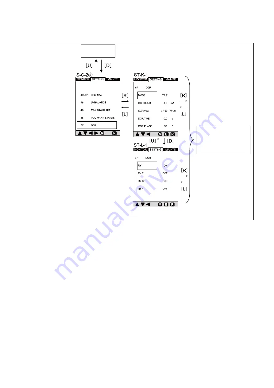
Figure 16-4 shows how to navigate between setting item screens (from S-C-2

 through to ST-L-1). See Table 11-4 for items that 

are actually displayed on the screen. 


Figure 16-4 Navigating between setting item screens (from S-C-2

  through to ST-L-1) 


You  can  set  each 

item in the same way 

as (a). 

S-C-2


Содержание TemTripPRO

Страница 1: ...OTOR PROTECTIVE RELAY Type PRS 1S INSTRUCTION MANUAL Be sure to read this instruction manual before using the product Keep this manual handy and safely Make sure that the product is set adjusted or tested by a competent person ...

Страница 2: ... 20 7 4 2 Navigating between password setting authentication screens from SU L 1 through to P A 4 23 7 4 3 Navigating between setting item screens from S A 1 through to ST A2 3 25 7 4 3 1 Navigating between setting item screens from S B 2 through to ST B2 1 27 7 4 3 2 Navigating between setting item screens from S B 2 through to ST C2 1 29 7 4 3 3 Navigating between setting item screens from S C 1...

Страница 3: ...humidity dusty air corrosive gases strong vibration and shock or other unusual conditions Storage temperature 25 C to 75 C Maintain the ambient temperature in a range of 10 C to 55 C and the ambient humidity in a range of 30 to 90 RH 15 C to 35 C without condensation Failure to do so may result in malfunction Before cleaning first turn the power OFF use towels twisted to be dry after soaked with w...

Страница 4: ...5 3 7 5 Control power supply Required 1 Two modes are available one where the protective relay is tripped and operation indication is provided and the other where the protective relay is not tripped and no operation indication is provided 2 Either of the following modes is available one where the protective relay is not tripped and only operation indication is provided and the other where the prot...

Страница 5: ...A 0 1A However 0 30 x Ict or more Zero phase voltage 190V Not adjustable Trip activation time setting 4 00 10 00 X In or OFF 0 10 Input setting 1 IN1 Remote Reset External fault 1 NO External fault 1 NC Input setting 2 IN2 Remote Reset External fault 2 NO External fault 2 NC AN OUT ADJ 4 20 90 0 110 0 0 1 4 mA 0 output adjustment 90 0 110 0 0 1 20 mA output adjustment 1 00 1 20 X Ict 0 01 Full ran...

Страница 6: ...s 0 5s 0 1 0s DEAD BAND 0 005 0 050 X Ict when the motor is about to turn ON 0 001 Undercurrent protection setting LVL2 High current TRIP ALARM OFF 0 20 1 50 X In 0 5 1 60 s 0 01 3 relative to the CT rating 1s 5 0 1 0s The relay is activated when a current value above the set value continues for the specified time limit or longer with the motor in a running state Startup disabled time 0 0 30 0 s 0...

Страница 7: ...ld motor Motor time constant ratio 1 15 1 This element sets the ratio of the time constant of cooling for a stopped motor and the time constant of heating cooling for a running motor Motor heating detection setting LVL1 TRIP ALARM OFF 0 50 0 99 X max Thermal capacity 0 01 This function simulates motor heating status Heating is related to the square of the maximum phase current The percentage of co...

Страница 8: ...hin 90 of 3V Temperature sensor RTD THERMISTOR 1 Type NTC PTC 2 Temperature sensor detection LVL1 TRIP ALARM OFF 0 250 1 1 1 TEMP1 When RTD is set 0 1 30 0 kΩ 0 1kΩ 5 0 1kΩ OHM1 When THERMISTOR is set 0 60 s 1s 5 0 1 0s Temperature sensor detection LVL2 TRIP ALARM OFF 0 250 1 1 1 TEMP2 When RTD is set 0 1 30 0 kΩ 0 1kΩ 5 0 1kΩ OHM2 When THERMISTOR is set 0 60 s 1s 5 0 1 0s Negative phase sequence ...

Страница 9: ... Curve Figure 1 shows the operating characteristic curve of the protective relay Motor heating trip Overload trip Short time delay trip Trip caused by unbalanced current Figure 1 Operating characteristic curve of the protective relay ...

Страница 10: ...n while the internal CPU is operating MOTOR lamp Lit in green while the motor is running Blinking in green while the motor is starting TRIP ALARM lamp Lit in red when tripping occurs or blinking in red when an alarm occurs MENU button Used to switch the screen ENTER button Used to change the set values RESET button Used to reset the relay or extinguish the LEDs Control circuit terminals For specif...

Страница 11: ...nsert mounting tool into mounting tool insertion groove 2 position above and below Mounting tool insertion groove Protective relay Mounting tool Panel surface Use a hexagon wrench to tighten the mounting screws tighttening torque 20 to 30 cN m secure the body 2 position above and below Hexagonal wrench Screw of mounting tool Flatblade screwdriver Use a hexagon wrench to loosen the mounting screws ...

Страница 12: ...specifications with communication facility SG For only specifications with communication facility Operation signal output 2 RY 1 COMMON Normally closed contact NC Normally open contact NO RY 2 COMMON Normally closed contact NC Normally open contact NO RY 3 COMMON Normally closed contact NC Normally open contact NO RY 4 COMMON Normally closed contact NC Normally open contact NO CPU operating status...

Страница 13: ...r Release the release button with the wires inserted Figure 6 1 Connecting to input terminals Figure 6 2 Control circuit terminal numbers of Tem Trip PRO and wire sizes for each connector used Terminal No Connector Wire size mm2 Wire stripping length mm Solid wire Stranded wire 1 12 0 2 2 25 0 2 2 25 7 13 15 0 2 0 75 0 2 0 75 7 16 17 0 2 0 75 0 2 0 75 7 18 20 0 2 1 25 0 2 1 25 7 21 27 0 2 2 0 0 2 ...

Страница 14: ...in total are used to display measured values and set characteristics In the figures shown in Sections 7 2 to 7 7 the following button symbols are used to indicate the buttons that must be pressed Button symbols and their descriptions M Press the MENU button U Press the up arrow button D Press the down arrow button R Press the right arrow button L Press the left arrow button E Press the ENTER butto...

Страница 15: ...creen INI A 1 is displayed after the power is turned on Measured value display items refer to 7 3 This screen allows you to view various currents line voltage phase voltage electrical power demand power electrical energy power factor and other measured values Characteristic value setting items refer to 7 4 This screen allows you to view the rated voltage CT rated primary current or other specifica...

Страница 16: ... 1 through to MO G 2 Figure 9 shows how to navigate between measured value display item screens from MO A 1 through to MO G 2 See Table 4 for items that are actually displayed on the screen Figure 9 Navigating between measured value display item screens from MO A 1 through to MO G 2 ...

Страница 17: ...ture sensor 1 Temperature value measured by RTD platinum resistance temperature detector RTD T2 Temperature measured by temperature sensor 2 RTD T3 Temperature measured by temperature sensor 3 MO F 1 THERMISTOR T1 Temperature measured by temperature sensor 1 Temperature value measured by thermistor THERMISTOR T2 Temperature measured by temperature sensor 2 THERMISTOR T3 Temperature measured by tem...

Страница 18: ...s how to navigate between characteristic value setting item screens from S A 1 through to S D 1 See Table 5 for items that are actually displayed on the screen Figure 10 Navigating between characteristic value setting item screens from S A 1 through to S D 1 See the setup screens in 7 4 1 See the setting screens in 7 4 3 ...

Страница 19: ... O C LVL2 SHORT Short circuit protection setting S C 1 THERMAL Motor heating detection setting UNBALANCE Unbalanced current protection setting MAX START TIME Motor startup time monitor setting TOO MANY STAR Motor startup count monitor setting DGR Ground fault detection setting S D 1 TEMPERATURE Temperature sensor detection setting PHASE LOSS Open phase protection setting HIGH LOW CURRENT Undercurr...

Страница 20: ...can use the U or D button to change the value SU A 3 SU A 4 A preliminary decision is made to update the value to 1400 At this stage the value is yet to be updated SU A 4 SU A 2 1 The value is updated to 1400 SU A 4 SU A 2 The value reverts to the original value 1400 If you have updated the value above replace SU A 1 and SU A 2 with SU A 1 1 and SU A 2 1 respectively in the following description Y...

Страница 21: ... 21 KRB 5426c Figure 11 1 Navigating between setup item screens from SU E 1 through to SU M 1 You can set each item in the same way as a above SU L 1 SU D 1 ...

Страница 22: ... the measured value displayed SU E 1 TRIP INHIBIT Trip activation disable setting 4 00 10 00 x In OFF CONFIG INPUT1 External input 1 setting Remote Reset External Fault1NO External Fault1 NC CONFIG INPUT2 External input 2 setting Remote Reset External Fault2 NO External Fault2 NC SU F 1 FULL RANGE 20 mA output setting 1 1 2 Ict FULL ADJUST 20 mA output adjustment 90 0 110 0 ZERO ADJUST 4 mA 0 outp...

Страница 23: ...g range Remarks SU L 1 Password change mode Initial display SU L 2 Password setting 1st digit 0 9 With the cursor staying in one of the digits pressing the U arrow button increments the number in the digit or pressing the D arrow button decrements the number in the digit SU L 3 Password setting 2nd digit 0 9 SU L 4 Password setting 3rd digit 0 9 SU L 5 Password setting 4th digit 0 9 SU L 6 Checkin...

Страница 24: ...password authentication screens from P A 1 through to P A 4 Table 7 1 Setting items and display details of password authentication screens P A 1 to P A 4 Screen No Display setting item Setting range Remarks P A 1 Password input 1st digit 0 9 With the cursor staying in one of the digits pressing the U arrow button increments the number in the digit or pressing the D arrow button decrements the numb...

Страница 25: ... between setting item screens from S A 1 through to AT A2 3 See Table 8 for items that are actually displayed on the screen Figure 13 Navigating between setting item screens from S A 1 through to AT A2 3 See the setting screens in 7 4 3 4 See the setting screens in 7 4 3 3 You can set each item in the same way as a S B 2 ...

Страница 26: ...e R arrow button and then use the U or D arrow button to set a mode or numerical value The procedure is the same as that described on page 20 ST A 2 L I CURR Trip pickup current value setting 1 00 1 50 x In ST A2 1 External output setting item switching Use the U or D arrow button to switch the item to be set The procedure is the same as that described on page 20 ST A2 2 RY1 External output settin...

Страница 27: ... to ST B2 1 Figure 14 shows how to navigate between setting item screens from S B 2 to ST B2 1 See Table 9 for items that are actually displayed on the screen Figure 14 Navigating between setting item screens from S B 2 through to ST B2 1 You can set each item in the same way as a ...

Страница 28: ...alues The procedure is the same as that described on page 20 ST B 1 O C L1 CURR Trip pickup current value setting 1 00 5 00 xIn ST B 1 O C L1 TIME Activation time limit setting 0 5 10 0 s ST B2 1 External output setting item selection setting Use the U or D arrow button to select the item to be set and press the R arrow button and then change the output settings The procedure is the same as that d...

Страница 29: ...ST C2 1 Figure 15 shows how to navigate between setting item screens from S B 2 through to ST C2 1 See Table 10 for items that are actually displayed on the screen Figure 15 Navigating between setting item screens from S B 2 through to ST C2 1 You can set each item in the same way as a ...

Страница 30: ...l values The procedure is the same as that described on page 20 ST C 1 O C L2 CURR Trip pickup current value setting 4 00 12 00 x In ST C 1 O C L2 TIME Activation time limit setting 0 0 4 0 s ST C2 1 External output setting item selection setting Use the U or D arrow button to select the item to be set and press the R arrow button and then change the output settings The procedure is the same as th...

Страница 31: ... L 1 Figures 16 shows how to navigate between setup item screens from S C 1 through to ST F2 1 See Table 11 for items that are actually displayed on the screen Figure 16 Navigating between setting item screens from S C 1 through to ST F2 1 You can set each item in the same way as a S C 2 ...

Страница 32: ...ty setting 0 50 0 99 x Motor heat capacity ST E2 1 External output setting item selection setting Use the U or D arrow button to select the item to be set and press the R arrow button and then change the output settings The procedure is the same as that described on page 20 RY1 External output setting ON OFF This setting item specifies whether to output to terminal number 1 RY2 ON OFF This setting...

Страница 33: ...n setting item screens from S C 2 through to ST H2 1 See Table 11 1 for items that are actually displayed on the screen Figure 16 1 Navigating between setting item screens from S C 2 through to ST H2 1 S C 2 S C 2 You can set each item in the same way as a ...

Страница 34: ...tection setting LVL2 Mode current value operating time setting This screen is displayed when you press the D arrow button with RY4 selected on the ST G2 1 screen The figure on the previous page shows the state in which trip pickup current value setting U B L2 CURR is selected You can use the U or D arrow button to select other items MODE Unbalanced current protection setting LVL2 mode setting TRIP...

Страница 35: ...ting item screens from S C 2 through to ST J2 1 See Tables 11 2 and 11 3 for items that are actually displayed on the screen Figure 16 2 Navigating between setting item screens from S C 2 through to ST J2 1 S C 2 S C 2 You can set each item in the same way as a ...

Страница 36: ...ng item screens S C 2 to ST J2 1 motor startup count monitor setting External output setting screen number Setting items and display details Selection Setting range Remarks Display Item S C 2 Setting item selection switching This screen is displayed when you press the D arrow button once at the S C 2 screen shown on page 35 ST J 1 Setting item selection switching The figure on the previous page sh...

Страница 37: ...tween setting item screens from S C 2 through to ST L 1 See Table 11 4 for items that are actually displayed on the screen Figure 16 4 Navigating between setting item screens from S C 2 through to ST L 1 You can set each item in the same way as a S C 2 ...

Страница 38: ...item by pressing the D arrow button once and then the R arrow button at this screen Use the U or D arrow button to increment or decrement the value to be set DGR TIME Ground fault detection time setting 0 1 10 0 s This setting item specifies the length of time during which ground fault must be detected You can select this setting item by pressing the D arrow button twice and then the R arrow butto...

Страница 39: ...17 Navigating between setting item screens from S D 1 through to ST N2 1 You can set each item in the same way as a Screen transition differs according to the TEMP SENSOR temperature sensor type setting When RTD is set ST M 1 1 ST M2 1 In the ST M 1 1 screen setting item SENSOR TYPE is fixed as PTC This setting cannot be changed When THERMISTOR is set ST M 1 2 ST O 1 In the ST M 1 2 screen setting...

Страница 40: ...ection setting This screen is displayed when you press the D arrow button with TEMPL1 TIME selected on the ST M2 1 or ST O 1 screen Use the U or D arrow button to select the item to be set and press the R arrow button and then change the output settings The setting procedure is the same as that described on page 20 RY1 External output setting ON OFF This setting item specifies whether to output to...

Страница 41: ...g item screens from S D 2 through to ST S 1 See Tables 12 1 and 12 2 for items that are actually displayed on the screen Figure 17 1 Navigating between setting item screens from S D 2 through to ST S 1 You can set each item in the same way as a S D 2 ST T 1 S D 2 ...

Страница 42: ...ST S 1 undercurrent protection setting Screen number Setting items and display details Selection Setting range Remarks Display Item ST D 2 Setting item selection switching This screen is displayed when you press the D arrow button once at the S D 2 screen shown on page 41 Use the U or D arrow button to select a desired setting item ST R 1 Undercurrent protection setting item selection setting The ...

Страница 43: ...tting item screens from S D 2 through to ST X2 1 See Table 12 3 for items that are actually displayed on the screen Figure 17 2 Navigating between setting item screens from S D 2 through to ST X2 1 S D 2 ST N2 1 S D 2 You can set each item in the same way as a ...

Страница 44: ... be set ST U 1 Undercurrent protection output setting item selection setting This screen is displayed when you press the D arrow button with H C DEAD BAND selected on the ST T 1 screen Use the U or D arrow button to select the item to be set and press the R arrow button and then change the output settings The setting procedure is the same as that described on page 20 RY1 External output setting ON...

Страница 45: ...tween setting item screens from S D 2 through to ST W 1 See Table 12 5 for items that are actually displayed on the screen Figure 17 3 Navigating between setting item screens from S D 2 through to ST W 1 S D 2 You can set each item in the same way as a ...

Страница 46: ...to output to terminal number 1 RY2 ON OFF This setting item specifies whether to output to terminal number 4 RY3 ON OFF This setting item specifies whether to output to terminal number 7 RY4 ON OFF This setting item specifies whether to output to terminal number 10 ST W0 MODE External anomaly protection 2 mode setting TRIP ALARM OFF This screen is displayed when you press the D arrow button with R...

Страница 47: ...vigating between maintenance item screens from MA A 1 through to MA E 2 MA A 1 When you navigate from the MA A 1 screen to the MA D 1 screen your password needs authentication Refer to 7 4 2 Test ends or L is pressed to cancel E is pressed to execute or L is pressed to cancel E is pressed to erase logs or L is pressed to cancel E is pressed to erase logs or L is pressed to cancel Refer to 7 7 Func...

Страница 48: ...and display details of maintenance item screens MA A 1 to MA D 2 historical data clearing Screen number Setting items and display details Remarks MA A 1 Maintenance items This screen is displayed when you press the D arrow button once at the MA A 1 screen shown on page 47 The figure on the previous page shows the state in which the historical data clearing item DATA CLEAR is selected MA D 1 Histor...

Страница 49: ...ance item screens from MA A 1 to MA H 41 For items that are actually displayed on the screen refer to Table 13 3 and 7 8 History and Trip Alarm Activation Display Screens Figure 18 1 Navigating between maintenance item screens from MA A 1 through to MA H 41 MA A 1 ...

Страница 50: ...00 events in chronological order The screen shown on the previous page displays five histories Use the U or D arrow button to switch the histories to be displayed MA G 2 to MA G 21 ALARM HISTORY Alarm activation history This screen displays the occurrence times causes phases concerned values and operating times for the recorded alarm activations up to 100 events in chronological order The screen s...

Страница 51: ...ich communication status display COMM is selected MA I 1 Status of communication with communication device on the reception side When data is received normally the count in the OK field on the screen is incremented When data is not received normally the count in the NG PARITY or NG CRC field on the screen is incremented MA I 2 Status of communication with communication device on the transmission s...

Страница 52: ...ivations Pressing M returns the display to the pre activation screen For the display details of the trip or alarm activation screen refer to 7 8 History and Trip Alarm Activation Display Screens Figure 19 Screen transition in the event of trip TR A 1 Figure 19 1 Screen transition in the event of alarm AL A 1 Screen before trip occurs Screen before alarm occurs ...

Страница 53: ...Updated ALARM Screen in the event of alarm activation AL A 1 Blinking in red Activated Updated NON TRIP TRIP MA B 1 Lit in red Not activated Not updated ALARM MA B 1 Blinking in red Not activated Not updated Figure 20 Screen transition for function test from MA B 1 to AL A 1 1 In the following cases after E is pressed no test is started and the display returns to the MA B 1 screen When the functio...

Страница 54: ...When relay output occurs an R mark appears on the bottom right of the screen To perform a reset press R When pulse output is used an automatic reset occurs Figure 20 1 Screen transition for relay test from MA C 1 to MA C 2 1 Even if you press E during relay output the relay will not be activated RY1 to RY4 can be selected ...

Страница 55: ...ages for the cause of each activation and the units of values and times displayed Cause of trip alarm activation display Message CAUSE Value that caused trip alarm activation to be displayed VALUE Occurrence time period that caused trip alarm activation to be displayed TIME Latest trip history screen Trip history list screen Trip alarm activation display screen Max Start Time MAX ST TIME MST MAX S...

Страница 56: ...T TRIP HISTORY RESET Alarm history reset ALARM HISTORY RESET ALARM HISTORY RESET Reset button pressed RESET BUTTON PRESSED RESET BUTTON PRESSED Relay test executed RY TEST RY TEST 7 9 Responses to Abnormal Events If internal CT circuit wiring is broken or another similar problem occurs the system will blink the TRIP or ALARM LED without outputting data and will be reset automatically when it becom...

Страница 57: ...mihigashi Hiranoku Osaka 547 0002 Japan Tel 81 6 6791 2763 Fax 81 6 6791 2732 Web Site http www terasaki co jp E mail kiki info terasaki co jp Published in Mar 2020 The contents of this manual may be subject to change without notice Recycle paper used ...

Отзывы: