PLDC04348
REVISION DATE
November 09, 2020
DATE
November 06, 2020
TECHNICAL OFFICE
S6 / Scout 6
T
ECHNICAL
S
ERVICE
M
ANUAL
Страница 1: ...PLDC04348 REVISION DATE November 09 2020 DATE November 06 2020 TECHNICAL OFFICE S6 Scout 6 TECHNICAL SERVICE MANUAL...
Страница 2: ......
Страница 3: ...brush 23 A3 1 Checking the power draw of the brushes Up Down actuator 25 A3 2 Replacing the brushes actuator 27 B1 1 Checking suction motor current draw 30 B1 2 Removing the suction motor 31 B2 1 Chec...
Страница 4: ...PLDC04348 REVISION 00 November 09 2020 TECHNICAL OFFICE...
Страница 5: ...the emergency switch Disconnect the electronic circuit from the batteries by detaching one or both battery connectors i INFORMATION Important information When consulting this Service manual the reade...
Страница 6: ...power 80W and maximum speed 2500 rpm The motor is of totally enclosed design affording optimum protection against the penetration of solids but not against the ingress of liquids accordingly the mach...
Страница 7: ...ith those indicated in the table proceed to make the following checks 10 Disassemble the side brush and check that the current draw under no load conditions is within the values in table 10a Should th...
Страница 8: ...jet of compressed air 4 Undo the fixing screws of the top cover and open the cover 5 Disconnect the two connectors red and black 6 Undo the 2 safety straps securing the battery 7 Remove the battery T...
Страница 9: ...tach the fixture 9 Remove the bush from the left hand arm 10 Remove the left bottom lateral guard and shift the arm drawing it way from its usual position 11 Position the machine on its left hand side...
Страница 10: ...move the side brush motor and loosen the hex head screw to remove the bracket 7 In order to release the belt the motor pulley must be moved toward the pulley of the centre brush accordingly loosen the...
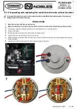
Страница 11: ...orking area with a jet of compressed air or a vacuum cleaner 4 Remove the battery 5 Identify the white connector of the brush motor and disconnect it 6 Unscrew the two nuts and remove the motor end ca...
Страница 12: ...the sliding contact surface which must present no indications of abnormal wear or of scorching 14 Blow the inside of the motor clean with a jet of compressed air paying particular attention to the are...
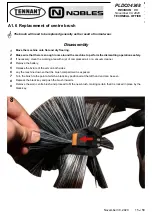
Страница 13: ...which the old leads were removed 2 Shift the springs to facilitate the insertion of the new brushes 3 Offer the end cap to the motor frame and slide almost fully into place then position the springs...
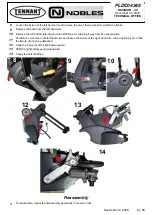
Страница 14: ...e right lateral guard 7 Shift the right bottom guard downwards 8 Undo the 2 hex head screws securing the motor to the mounting Shift the motor toward the centre brush so as to slacken off the drive be...
Страница 15: ...jet of compressed air or a vacuum cleaner 4 Remove the battery 5 Release the fixture of the arm on both sides 6 Lay the machine down so that the brush compartment is exposed 7 Turn the brush to the po...
Страница 16: ...of the motor is 30W whilst the voltage is 24 Vdc albeit a 12 Vdc input is utilized as in the case of the centre brush motor in effect the two motors are connected together but wired with the polarity...
Страница 17: ...einstate the top cover of the machine 9 Conversely if the value is at variance with those indicated in the table proceed to make the following checks 10 Disassemble the side brush and check that the c...
Страница 18: ...d be either blasting with compressed air or using a vacuum cleaner 4 Remove the battery 5 Shift the right bottom guard downwards 6 Proceed to detach the brush motor as described in the heading below 7...
Страница 19: ...of the bearing 12 Remove the bearing from its seat using two screwdrivers as levers to apply pressure from beneath should the bearing prove difficult to dislodge from the shaft use a small puller 13...
Страница 20: ...of the sliding contact surface which must present no indications of abnormal wear or of scorching 18 Blow the inside of the motor clean with a jet of compressed air paying particular attention to the...
Страница 21: ...into the slots so as to facilitate reassembly 5 Offer the carbon brushes to the rotor and free them from the slots ensuring that they bear against the rotor 6 Refit the bearing to the motor shaft and...
Страница 22: ...it 8 Remove the wall bumper wheel by sliding it off the relative pivot 9 Undo the hex head screw securing the plastic hub of the side brush to the motor and remove the plastic bushing 10 Undo the 3 h...
Страница 23: ...fely 3 Undo the fixing screws of the top cover and remove the cover 4 Turn the height adjustment knob to raise or lower the side brush to the correct position 5 When adjustment is complete the positio...
Страница 24: ...on against ingress of solids and liquids is IP44 The maximum force applicable when raising and lowering the brushes is 72 kg 5 kg The stroke of the actuator rod is factory set to 65 mm by means of two...
Страница 25: ...d take out the F5 fuse 6 Use a digital multimeter and select Continuity mode 7 Position the red probe on one end of the fuse the black probe on the other end and check that the multimeter emits a cont...
Страница 26: ...t speed 2 selected by way of the control panel 13 If the brush is not lowered when started up or not raised when shut off and there is no power draw check the continuity of all wires in the intercable...
Страница 27: ...of compressed air or a vacuum cleaner 4 Undo the fixing screws of the top cover and open the cover 5 Disconnect the two battery connectors red and black 6 Locate the power connector of the actuator an...
Страница 28: ...the emergency switch Disconnect the electronic circuit from the batteries by detaching one or both battery connectors i INFORMATION Important information When consulting this Service manual the reade...
Страница 29: ...er The suction unit is a centrifugal type with a rated flow of 67 litres s 142 CFM and vacuum capability of 5 0 mm H2O 0 2 in H2O 0 007 PSI The motor is a brushed type equipped with two non replaceabl...
Страница 30: ...the Red wire of the suction motor and apply the clamp on ammeter to it 7 Run the suction motor by selecting the relative key on the control panel 8 Take note of the reading on the ammeter display and...
Страница 31: ...necessary clean the working area with a jet of compressed air or a vacuum cleaner 4 Undo the fixing screws of the top cover and remove the cover 5 Remove the battery 6 Remove the dirt bin 7 Remove th...
Страница 32: ...n housing and the relative frame to a bench and proceed with disassembly 14 To separate the shaker frame from the fan housing the 4 wires must be detached from the connector and drawn through the hole...
Страница 33: ...NICAL OFFICE November 30 2020 33 of 58 Reassembly 1 To refit the suction motor repeat the disassembly steps described above in reverse order 2 Take care when locating the pins of the filter shaker mot...
Страница 34: ...filter shaker can be operated in manual mode using the dedicated button on the control panel and orin automatic modeifprogrammedusingtherelativefacilityprovidedbythedisplay pcb The display offers the...
Страница 35: ...scale reading of at least 200 A amperes 6 Pick out the Red wire of the filter shaker motor and apply the clamp on ammeter to it 7 Activate the filter shaker with the relative key on the control panel...
Страница 36: ...rking area with a jet of compressed air or a vacuum cleaner 4 Undo the fixing screws of the top cover and remove the cover 5 Disassemble the suction unit so as to access the filter shaker as described...
Страница 37: ...g the emergency switch Disconnect the electronic circuit from the batteries by detaching one or both battery connectors i INFORMATION Important information When consulting this Service manual the read...
Страница 38: ...area with a jet of compressed air or a vacuum cleaner 4 Undo the fixing screws of the top cover and remove the cover 5 Remove the battery 6 Raise the arm and lock in the upright position at 90 to the...
Страница 39: ...y switch Disconnect the electronic circuit from the batteries by detaching one or both battery connectors i INFORMATION Important information When consulting this Service manual the reader will encoun...
Страница 40: ...he control panel Program 1 or Program 2 Consequently the current draw will be different for each of the two settings greater in the case of Program 2 The instantaneous power draw of the brushes can be...
Страница 41: ...he machine to perform the dismantling operations safely 3 Undo the fixing screws of the top cover and remove the cover 4 Undo the hex head screw and remove the protective plastic cover of the power ci...
Страница 42: ...safely 3 Undo the fixing screws of the top cover and remove the cover 4 Disconnect the two battery connectors red and black 5 Undo the hex head screw to remove the protective plastic cover and disconn...
Страница 43: ...48 REVISION 00 November 09 2020 TECHNICAL OFFICE Reassembly 1 To reassemble the power circuit board repeat the disassembly steps in reverse order 2 Take care when connecting the 2 wires of the circuit...
Страница 44: ...programs however it is not recommended to modify these and the filter shaker activation times There is then another more technical part to change some essential parameters such as the type of battery...
Страница 45: ...n A until the display switches off Parameter Indications and Available Values P1 X Brush pressure program 1 with value X from 0 to 5 It is not recommended to change the default value P2 X Brush pressu...
Страница 46: ...tches off Parameter Indications and Available Values U1 X Actuator reaction time program 1 with value X from 0 to 9 It is not recommended to change the default value U2 X Actuator reaction time progra...
Страница 47: ...denotes that the battery is fully charged The display circuit board is interfaced with the power circuit board by way of the 8 pin connector AMP 2 and supplied with power directly from the power pcb t...
Страница 48: ...safely 3 Undo the fixing screws of the top cover and remove the cover 4 Disconnect the two battery connectors red and black 5 Undo the 5 screws securing the top shroud of the control panel to the bot...
Страница 49: ...room around the machine to perform the test safely 3 Undo the fixing screws of the top cover and remove the cover 4 Disconnect the two battery connectors red and black 5 Expose the display circuit boa...
Страница 50: ...machine to perform the test safely 3 Undo the fixing screws of the top cover and remove the cover 4 Disconnect the two battery connectors red and black 5 Expose the display circuit board as described...
Страница 51: ...ICAL OFFICE D2 ELECTRICAL SYSTEM M1 MAIN BRUSH M2 SIDE BRUSH M3 FAN M4 FILTER SHAKER M5 BRUSH ACTUATOR FUSE F1 20A MAIN BOARD DISPLAY 12V BATTERY 115Vac PLUG TRANSFORMER 12Vac FUSE F6 1 25A T BATTERY...
Страница 52: ...rgency switch Disconnect the electronic circuit from the batteries by detaching one or both battery connectors i INFORMATION Important information When consulting this Service manual the reader will e...
Страница 53: ...not switch on 1 Switch on the suction motor only A If motor starts up go to point 2 B If motor fails to start go to point 5 2 Check for correct assembly of filter A If assembly is wrong reassemble co...
Страница 54: ...A If brush rotates correctly go to point 2 B If brush rotates but in the wrong direction invert the wires at the connector only if brush motor has been replaced C Only if centre brush does not rotate...
Страница 55: ...eadings are not as expected replace the display circuit board E1 1 6 Side brush not rotating 1 Disconnect centre brush motor from main wiring loom and connect directly to battery A If motor does not t...
Страница 56: ...ted replace the power circuit board B If voltage reading is not as expected replace the display circuit board E1 1 7 Suction not working 1 Disconnect filter shaker motor from main wiring loom and conn...
Страница 57: ...es SP1 Brushes KO Error resettable only by switching off the machine Trips if the brushes cut out SHUTDOWN three times within the space of one minute cP Communication Problem Communication error betwe...