background image

MAINTENANCE

810D MM310 (3--95)

70

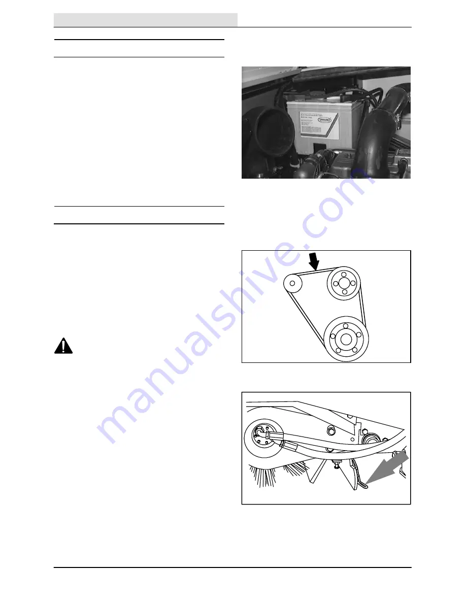
BATTERY

The battery for the machine is a low maintenance

battery. Do not add water to the battery, or

remove the battery vent plugs.

The battery is located under the hydraulic

reservoir for machines below serial number

002074, and in the engine compartment for

machines serial 002074 and above.

After the first 50 hours of operation, and every

800 hours after that, clean and tighten the battery

connections.

BELTS AND CHAINS

ENGINE BELT

The engine fan belt is driven by the engine

crankshaft pulley and drives the alternator pulley.

Proper belt tension is 9 to 10 mm (0.35 to

0.39 in) for a new belt and 10 to 11 mm (0.39

to 0.43 in) for a used belt with a force of

10 kg (22 lb).

Check and adjust the belt tension every 100 hours

of operation.

WARNING: Moving belt and fan. Keep

away.

STATIC DRAG CHAIN

A static drag chain prevents the buildup of static

electricity in the machine. The chain is attached to

the machine by a rear main brush skirt retaining

bolt.

Make sure the chain is touching the floor at all

times.

08486

08449

Содержание 810D

Страница 1: ...810D MM310 Operator Manual...

Страница 2: ...cing it This machine will provide excellent service However the best results will be obtained at minimum costs if D The machine is operated with reasonable care D The machine is maintained regularly p...

Страница 3: ...EL LEVEL GAUGE 21 HOURMETER 22 HAZARD LIGHT SWITCH OPTION 22 OPERATING LIGHTS SWITCH 22 FILTER SHAKER SWITCH 23 VACUUM FAN SWITCH 23 IGNITION SWITCH 24 Page MAIN BRUSH AND POWER THROWt SWITCH 25 STEER...

Страница 4: ...71 HOPPER DUST FILTER 71 TO REMOVE OR REPLACE HOPPER DUST FILTER 71 THERMO SENTRYt 73 Page BRUSHES 73 MAIN BRUSH 73 TO REPLACE MAIN BRUSH 73 TO CHECK AND ADJUST MAIN BRUSH PATTERN 74 POWER THROWt 77...

Страница 5: ...low on inclines and slippery surfaces use care when reversing machine move machine with care when hopper is raised make sure adequate clearance is available before raising hopper do not carry passenge...

Страница 6: ...ARMS LABEL LOCATED ON BOTH HOPPER LIFT ARMS HOPPER SUPPORT BAR LABEL LOCATED ON THE HOPPER LIFT ARMS CROSS TUBE AND ON BOTH HOPPER LIFT ARMS NOISE LABEL LOCATED ON THE FRONT PANEL OF THE OPERATOR COM...

Страница 7: ...ervisor when the required maintenance intervals occur as stated in the MAINTENANCE section of this manual Read this manual carefully before operating this machine FOR SAFETY Do not operate machine unl...

Страница 8: ...uel system service area Keep area well ventilated After the first 50 hours of operation follow the recommended procedures stated in the MAINTENANCE CHART Keep your machine regularly maintained by foll...

Страница 9: ...810D MM310 1 93 MACHINE COMPONENTS A B C D E F G H I 07623 A Operator Seat F Hopper Cover B Steering Wheel G Side Brush C Engine Cover H Instrument Panel D Engine Side Door I Hopper Door E Main Brush...

Страница 10: ...sure Light Hopper Temperature Thermo Sentryt Side Brush Down Pressure Heavy Main Brush Shut Down Side Brush Down and On Filter Clogged Side Brush Up and Off Hopper Door Closed Hopper Door Close Fuel H...

Страница 11: ...cuit Breaker 5 Main Brush Down Pressure Light Circuit Breaker 6 Main Brush Down Pressure Heavy Circuit Breaker 7 Circuit Breaker 1 Circuit Breaker 8 Circuit Breaker 2 Circuit Breaker 9 Circuit Breaker...

Страница 12: ...Light Switch Option F Side Brush Down Pressure Knob U Operating Light Switch G Hopper Door Lever V Filter Shaker Switch H Hopper Rollout Lever W Vacuum Fan Switch I Hopper Lift Lever X Ignition Switc...

Страница 13: ...e the speed of the machine with the pressure of your foot the harder you press the faster the machine travels Forward Press the top of the directional pedal with the toe of your foot Reverse Press the...

Страница 14: ...Take your foot off the directional pedal and let it return to the neutral position Step on the brake pedal PARKING BRAKE For machines below serial number 002046 The parking brake pedal sets and the l...

Страница 15: ...46 and above The parking brake lever sets and releases the front wheel brakes Set Pull the parking brake lever up FOR SAFETY Before leaving or servicing machine stop on level surface set parking brake...

Страница 16: ...OPERATION 810D MM310 6 94 14 THROTTLE LEVER The throttle lever controls the engine speed Fast Pull the lever into the Fast position Idle Push the lever into the Idle position 08456 08457...

Страница 17: ...l the side brush position lever back and to the left into the Off Up slot SIDE BRUSH SWITCH For machines serial number 002063 and above The right side brush switch controls the right side brush positi...

Страница 18: ...For machines below serial number 002063 Heavy Turn the side brush down pressure knob counter clockwise Light Turn the side brush down pressure knob clockwise For machines serial number 002063 and abov...

Страница 19: ...hopper door Close the hopper door when emptying the hopper to control debris and dust Open Pull and hold the hopper door lever in the Open position Hold Release the hopper door lever into the middle p...

Страница 20: ...hopper rollout lever moves the hopper in and out Out Pull and hold the hopper rollout lever in the Out position Hold Release the hopper rollout lever into the middle position In Push and hold the hopp...

Страница 21: ...he hopper lift lever in the Up position WARNING Raised hopper may fall Engage hopper support bar Hold Release the hopper lift lever up and into the middle position Lower Push and hold the hopper lift...

Страница 22: ...Stop operating the machine Locate the problem and have it corrected ENGINE WATER TEMPERATURE LIGHT The engine water temperature light comes on when the temperature of the engine coolant is more than 1...

Страница 23: ...s the filter shaker switch If the clogged filter light remains lit manually clean the hopper dust filter See HOPPER DUST FILTER in MAINTENANCE HOPPER DOOR LIGHT OPTION The hopper door light comes on w...

Страница 24: ...t On Press the hazard light switch The indicator light above the switch will come on Off Press the hazard light switch The indicator light above the switch will go off OPERATING LIGHTS SWITCH The oper...

Страница 25: ...shaker is operating Stop Press the filter shaker switch again IF wanting to stop the filter shaker during the 40 second shaking cycle NOTE The vacuum fan shuts off while the filter shaker is operating...

Страница 26: ...he key clockwise The glow plugs light will come on When the glow plug light goes out usually for 5 to 15 seconds depending on the weather conditions the engine is ready to start Start Turn the key all...

Страница 27: ...ols the main brush and Power Throwt brush positions and rotation Main Brush Down and Normal Speed Press the top Normal position of the switch Brushes Up and Off Place the switch in the middle Off posi...

Страница 28: ...Right Turn the steering wheel to the right STEERING WHEEL TILT LEVER The steering wheel tilt lever controls the angle of the steering wheel Adjust Pull out the tilt lever move the wheel up or down and...

Страница 29: ...roblem is corrected The circuit breakers are located in the operator compartment The chart lists the circuit breakers and the electrical components they protect Circuit Breaker Rating Circuit Protecte...

Страница 30: ...e Turn the main brush down pressure knob clockwise LATCHES The side doors rear door engine cover and hopper cover are secured with latches Open the Main Brush Side Doors Pull up on the door latch Open...

Страница 31: ...nob Adjust Turn the knob clockwise to increase the ride stiffness and counter clockwise to decrease the ride stiffness Lift Pull up on the seat mounting plate until the seat mount locks up Lower Pull...

Страница 32: ...On Press on the switch Off Press on the switch again RECIRCULATING AIR LOUVERS OPTION The optional recirculating air louvers recirculates the cab air through the temperature core This will maximize ei...

Страница 33: ...rates the cab s air conditioner in the optional cab On Turn the switch clockwise until the air temperature is at the desired comfort level For maximum cooling turn the switch clockwise all the way to...

Страница 34: ...ebris into the path of the main brush The Power Throwt brush is used to help pick up bulky debris The main brush sweeps debris from the floor into the hopper The vacuum system pulls dust and air throu...

Страница 35: ...OPERATION 33 810D MM310 3 95 Check the engine oil level Check fuel level Check the brakes and steering for proper operation 08431 07764 08471...

Страница 36: ...utral and your foot on the brake pedal or with the parking brake set 2 Move the throttle lever to the Idle position 3 Turn the key clockwise The glow plugs light will come on When the glow plug light...

Страница 37: ...tarting attempt or damage to the starter motor may occur 5 Allow the engine and hydraulic system to warm up three to five minutes WARNING Engine emits toxic gases Severe respiratory damage or asphyxia...

Страница 38: ...OPERATION 810D MM310 3 95 36 8 Drive the machine to the area to be swept 08580...

Страница 39: ...f the steering wheel Avoid sudden turns except in emergencies Use the Power Throwt when picking up light litter This will improve both litter pickup and hopper loading Do not use the Power Throwt spee...

Страница 40: ...excellent loading of light bulky debris leaves and paper while the nylon bristle gives long life Heavy Gauge Polypropylene 8 double Row Main Brush Designed for sweeping outdoor areas The stiffer brist...

Страница 41: ...be closed during sweeping If your machine has the hopper door light option make sure the hopper door light is off If the hopper door light is on close the hopper door 2 Place the main brush and Power...

Страница 42: ...63 pull the side brush position lever back and to the right into the On Down slot For machines serial number 002063 and above push the top of the side brush switch into the On Down position 4 Press th...

Страница 43: ...osition lever back and to the left into the Off Up slot For machines serial number 002063 and above push the bottom of the side brush switch into the Off Up position 2 Place the main brush switch in t...

Страница 44: ...ce is available before raising hopper NOTE Be aware that the minimum ceiling height needed to high dump the hopper is 3355 mm 11 ft 3 Release the hopper lift lever up and into the middle Hold position...

Страница 45: ...ntainer FOR SAFETY When using machine move machine with care when hopper is raised 10 Push and hold the hopper door lever into the Close position 11 Push and hold the hopper rollout lever into the In...

Страница 46: ...D MM310 11 95 44 STOP THE MACHINE 1 Stop sweeping 2 Take your foot off the directional pedal Step on the brake pedal 3 Move the throttle lever to the Idle position 4 Set the machine parking brake 0847...

Страница 47: ...0 11 95 5 Turn the ignition switch key counter clockwise to stop the engine Remove the switch key FOR SAFETY Before leaving or servicing machine stop on level surface set parking brake turn off machin...

Страница 48: ...and SIDE BRUSH in MAINTENANCE Check the brush skirts for damage wear and adjustment Check for wire or string tangled on the main and side brushes Check for fuel odor that indicates a fuel leak Check...

Страница 49: ...OPERATION 47 810D MM310 3 95 ENGAGING HOPPER SUPPORT BAR 1 Set the machine parking brake 2 Start the engine 3 Raise the hopper all the way up 08434 08460 08480...

Страница 50: ...he storage clip WARNING Raised hopper may fall Engage hopper support bar 5 Slowly lower the hopper so the support bar rests on the bar stop on the machine frame WARNING Lift arm pinch point Stay clear...

Страница 51: ...GAGING HOPPER SUPPORT BAR 1 Start the engine 2 Raise the hopper slightly to release the hopper support bar 3 Put the hopper support bar in the storage clip WARNING Lift arm pinch point Stay clear of h...

Страница 52: ...engine off OPERATION ON INCLINES Drive the machine slowly on inclines Use the brake pedal to control machine speed on descending inclines The maximum rated incline is 8 5_ FOR SAFETY When using machin...

Страница 53: ...machine FOR SAFETY Before leaving or servicing machine stop on level surface set parking brake turn off machine and remove key Block machine tires The two front tie down locations are through the U b...

Страница 54: ...debris that is out of reach of the machine 1 Stop the machine within reach of the area to be vacuumed and set the machine parking brake 2 Turn off the vacuum fan by pressing the vacuum fan switch The...

Страница 55: ...Off Up position 5 Open the forward hopper access door and engage the lift arm 6 Remove the vacuum plug from the vacuum adaptor tube in front of the hopper 7 Remove the vacuum wand and hose from the mo...

Страница 56: ...t into the locked position 10 Turn on the vacuum fan by pressing the vacuum fan switch The indicator light above the switch will go on 11 Vacuum the area as needed 12 When done vacuuming turn off the...

Страница 57: ...sition 14 Disconnect the vacuum hose from the vacuum adaptor tube in front of the hopper 15 Disassemble the vacuum hose assembly and place back onto the hopper in the mounting clips 16 Replace the vac...

Страница 58: ...ows the operator to blow debris out from areas while sweeping with the machine 1 Remove the blower attachment from the back of the machine 2 Move the blower wand lever on the lintle to the left into t...

Страница 59: ...ket The operator can also add the extension onto the end of the blower wand for extended reach 4 Move the blower wand lever on the lintle to the right into the OFF position to stop airflow through the...

Страница 60: ...eeping operation If the hopper is over full the light may come on Check the hopper load and dump if necessary If the filter light remains on after all the above conditions are corrected the filters ma...

Страница 61: ...completely closed Open the hopper door Thermo Sentryt tripped Reset Thermo Sentryt Fabric presceen missing on dust filters Clean filter elements and install fabric prescreen Poor sweeping performance...

Страница 62: ...gine air filter Check indicator 1 Empty dust cap 1 9 Engine crankcase Check oil level EO 1 15 Brush compartment skirts Check for damage wear and 6 adjustment 17 Hopper lip skirts Check for damage wear...

Страница 63: ...earings 7 Parking brake Check adjustment 1 3 Side brush pivot Lubricate SPL 1 400 Hours 12 Fuel filter Engine Replace 1 12 Water separator fuel filter Replace 1 9 Cooling system Flush WG 1 5 Brake mas...

Страница 64: ...e main brush compartment For machines serial number and above the engine oil drain is located on the engine oil pan Drain the engine oil when it is warm Fill the engine with oil to the level indicated...

Страница 65: ...BRUSH PIVOT PINS The side brush pivot pins should be lubricated with Lubriplate EMB grease TENNANT part no 01433 1 every 200 hours of operation MAIN BRUSH ADJUSTMENT The main brush adjustment located...

Страница 66: ...luid in the reservoir Lubricate the filler cap gasket with a film of hydraulic fluid before putting the cap back on the reservoir ATTENTION Do not overfill the hydraulic fluid reservoir or operate the...

Страница 67: ...ions match TENNANT hydraulic fluid specifications Using substitute fluids can cause premature failure of hydraulic components European marketed machines are filled with locally available hydraulic flu...

Страница 68: ...or block Keep the engine running while adding water Clean the radiator screen every 100 hours of operation Check the radiator hoses and clamps every 200 hours of operation Tighten the clamps if they a...

Страница 69: ...t cap daily The air filter must be replaced whenever the filter element is damaged or has been cleaned three times Machines with the heavy duty SE air filter option have a safety element It is inside...

Страница 70: ...used much or not Replace the fuel lines every two years If the fuel lines are found worn or damaged before two years time replace or repair them at once Bleed the fuel system after replacement of any...

Страница 71: ...lding down the priming pump tighten the return connection to the injection pump 11 Loosen all four of the high pressure fuel line connections at the atomizers ATTENTION The engine may start running sp...

Страница 72: ...connections BELTS AND CHAINS ENGINE BELT The engine fan belt is driven by the engine crankshaft pulley and drives the alternator pulley Proper belt tension is 9 to 10 mm 0 35 to 0 39 in for a new belt...

Страница 73: ...ust filter from the inside This may be done with the dust filter in the machine or for more efficient cleaning remove the dust filter from the machine and the prescreen wrap from the filter element Al...

Страница 74: ...he new filter element Put the new filter on the filter shaker frame 10 Place the retainer ring over the filter Make sure the retaining ring fits inside the lip of the filter element all the way around...

Страница 75: ...gled on the main brush main brush drive hub or main brush idler hub Check the main brush pattern daily The pattern should be 50 to 65 mm 2 to 2 5 in wide Adjust the main brush pattern by turning the m...

Страница 76: ...ive plug Rotate the brush until it engages the drive plug and push it all the way onto the plug 8 Slide the main brush idler plate plug onto the main brush 9 Latch the idler plate onto the machine fra...

Страница 77: ...to spin on the floor for two minutes A polish mark will remain on the floor 5 Raise the main brush 6 Stop the main brush 7 Drive the machine off the test area 8 Observe the width of the brush pattern...

Страница 78: ...e brush drive end plate mounting bolts B Turn the taper adjustment nut counter clockwise to increase the pattern width at the brush drive end and clockwise to decrease the pattern width at the brush d...

Страница 79: ...floor clearance and counter clockwise to decrease the floor clearance TO REPLACE POWER THROWt BRUSH 1 Set the machine parking brake FOR SAFETY Before leaving or servicing machine stop on level surface...

Страница 80: ...sweeps effectively for your application A guideline length is when the remaining bristles measure 50 mm 2 in in length You may change the side brush sooner if you are sweeping light litter or wear the...

Страница 81: ...lace the hopper lip skirts when they no longer touch the floor BRUSH COMPARTMENT SKIRTS The brush compartment skirts are located on the bottom of each of the two main brush doors and around the ends o...

Страница 82: ...es BRUSH DOOR SEALS The brush door seals are located on both main brush doors and on corresponding portions of the main frame Check the seals for wear or damage every 100 hours of operation HOPPER SEA...

Страница 83: ...pper filter compartment Check the seal for wear or damage every 100 hours of operation HOPPER COVER SEAL The hopper cover seals are located on the inside of the hopper cover They seal the hopper filte...

Страница 84: ...er brake cylinder fluid level every 400 hours of operation PARKING BRAKE The parking brake is set with foot pedal on machine below serial number 002046 and with a lever on machines serial number 00204...

Страница 85: ...b after the first 50 hours of operation and every 800 hours there after PUSHING OR TOWING MACHINE The propelling pump has a towing valve to prevent damage to the hydraulic system when the machine is b...

Страница 86: ...the machine frame next to the front tires The rear jacking location is the middle of the rear bumper FOR SAFETY When servicing machine block machine tires before jacking machine up FOR SAFETY When se...

Страница 87: ...wt brush diameter 205 mm 8 in Power Throwt brush length 1170 mm 46 in Side brush diameter 65 mm 26 in Sweeping path width 1270 mm 50 in Sweeping path width with side brush 1675 mm 66 in Main brush pat...

Страница 88: ...rpm Engine lubricating oil with filter 6 L 6 3 qt 10W30 SAE CC CD rated engine oil STEERING Type Power source Emergency steering Rear wheel hydraulic cylinder and rotary valve controlled Hydraulic acc...

Страница 89: ...25 Button Horn 19 C Cab Air conditioning switch 31 Air control vents 31 Dome light switch 30 Fan speed switch 31 Heater knob 30 Recirculating air louvers 30 Windshield wiper switch 30 Capacities 85 C...

Страница 90: ...0 Doors Brush Latch 28 Seals 80 Skirts 79 Engine side Latch 28 Grille Latch 28 Hopper Seals 80 Rear bumper Latch 28 Dust filter 71 Changing 71 72 Cleaning 71 E Electrical Circuit breakers 27 Ignition...

Страница 91: ...reservoir 64 Hydraulic hoses 65 Hydraulics 64 65 Fluid 65 Fluid filter 64 Fluid level 5 64 Hoses 65 Propelling motor 66 Reservoir 64 System specifications 86 I Ignition switch 24 J Jack points 84 K K...

Страница 92: ...on Hazard light switch 22 Options 52 59 Air conditioning switch 31 Air control vents 31 Blower wand 56 57 Blower wand lever 26 Dome light switch 30 Fan speed switch 31 Heater knob 30 Heavy duty SE air...

Страница 93: ...ensions 85 Machine performance 85 Power type 86 Steering 86 Tires 86 Starting the machine 34 35 Static drag chain 70 Steering 33 Specifications 86 Steering wheel 26 Steering wheel tilt lever 26 Stop s...

Страница 94: ...INDEX 810D MM310 3 95 92...

Отзывы: