Temptek BG-N4 Series Скачать руководство пользователя страница 57

BG-N4 Glycol Chiller

Page: 57

TEMPTEK, INC.

525 East Stop 18 Road Greenwood, Indiana 46142 

317-887-6352    Fax: 317-881-1277

Email: [email protected]

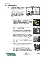
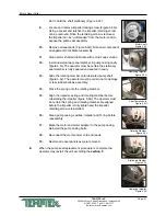
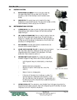
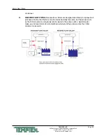
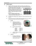
G. EVAPORATOR: The evaporator is a brazed plate heat 

exchanger where the refrigerant liquid is allowed to 

evaporate (boil off) to absorb heat (BTU) from the process 

fluid. As the heat is absorbed, the process fluid is chilled.

J. 

Liquid receiver: (optional feature) located after the 

condenser, this component receives and stores liquid 

refrigerant leaving the condenser.

H. 

Service valves: These valves are located throughout the 

system. Only a qualified refrigeration service technician 

shall operate these valves.
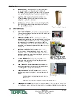
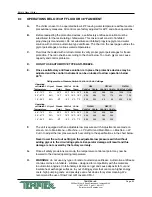
6.3  UNIT OPTIONS

A. 

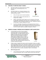
LOW FLOW BYPASS: If your process will experience lower 

than design flow rates or intermittent flow, a low flow bypass 

valve will be required.
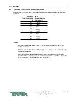
B. 

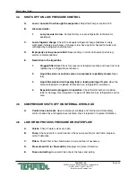
OVERHEAD PIPING KIT: To avoid reservoir overflow 

during shut down periods from overhead piping, The Factory 

recommends the installation of an overhead piping kit. The 

overhead piping kit consists of a full line size solenoid 

valve in the “from process” line that is interlocked with the 

pump and a check valve (single direction valve) in the “to 

process” line. 

C. 

PROCESS LINE SHUT OFF VALVES: These valves 

are full size ball valves installed on the “to” and “from” 

process lines at the exit of the chiller. These valves can 

be used to adjust the process flow rate and to shut off the 

flow rate to isolate the chiller.
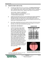
D. 

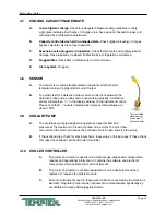
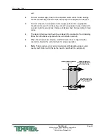
E-STOP BUTTON: The Emergency stop button is a 

mushroom type button which will shut down all chiller 

operations when engaged. 

E. 

NON-FUSED OR FUSED DISCONNECT SWITCH: On 

board disconnect switch provides a convenient location 

for isolating all electric power to the chiller.

F. 

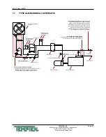
AUDIBLE AND OR VISUAL ALARM: Alarms indicate 

out-of-spec operating conditions. There are two types of 

alarms:

Audible Alarm: A simple buzzer alarm emits a 

loud alarm.

Visual Alarm: Emits an audible sound and flashes a beacon.
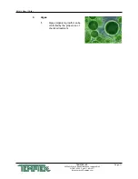
G. 

CONDENSER SCREEN: Optional for air-cooled models only. The condenser screen is a 

filter for the air-cooled condenser to prevent air borne solids and debris from clogging the 

Typical brazed plate evaporator

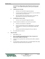
Typical optional automatic low 

flow bypass valve.

Emergency stop button. Shown with 

Power On light.

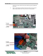
Typical overhead piping kit. Shown 

with optional process line shut off 

valves. Process line shut off valves 

are also shown in this photo.

Содержание BG-N4 Series

Страница 1: ...nstalled in a climate where the ambient temperature may get below 40 F you must use a water and glycol mixture at a ratio that protects the fluid from freezing to approximately 25 F below the lowest expected set point temperature or the lowest expected ambient temperature whichever is lower See Section 8 1 and 8 2 of this manual before operating your chiller Regular testing of your glycol protecti...

Страница 2: ......

Страница 3: ...COOLED MODELS COVERING INSTALLATION OPERATION MAINTENANCE BG N4 Series G l y c o l C h i l l e r TEMPTEK INC 525 East Stop 18 Road Greenwood IN 46142 Phone 317 887 6352 Fax 317 881 1277 Service Department fax 317 885 8683 www Temptek com e mail sales Temptek com ...

Страница 4: ...ts Menu 30 3 6 Instrument Utilities Menu 32 3 7 Instrument Network Menu 33 3 8 Instrument Flow Menu optional 34 3 9 Instrument Options Menu 35 3 10 Instrument Machine Menu 36 3 11 Shut Down Procedure 39 4 0 TROUBLESHOOTING 41 4 1 Unit Will Not Start 42 4 2 Compressor Hums But Will Not Start 42 4 3 Shuts Off On High Pressure 42 4 4 Shuts Off On Low Pressure 43 4 5 Compressor Shuts Off On Internal O...

Страница 5: ...INGS 59 7 1 Typical Mechanical Schematic 60 8 0 APPENDIX 61 8 1 Operations below 48 F fluid or 38 F ambient 62 8 2 Inhibited propylene glycol 63 8 3 Refrigerant pressure temperature chart 64 8 4 Chiller capacity and derate chart 65 8 5 Standard MG Instrument Settings 66 8 6 Probe Calibration MG Instrument 67 8 7 Status Indicators MG Instrument 69 8 8 Water Quality 70 8 9 Modbus Registers 72 8 10 R...

Страница 6: ...Page 6 THIS PAGE INTENTIONALLY BLANK ...

Страница 7: ...MPTEK INC 525 East Stop 18 Road Greenwood Indiana 46142 317 887 6352 Fax 317 881 1277 Email service Temptek com 1 0 GENERAL 1 1 Introduction 1 2 Safety 1 3 Receiving Instructions 1 4 Efficiency 1 5 Clean Air Act 1 6 Water Treatment ...

Страница 8: ... Refrigerant gas can cause toxic fumes if exposed to fire Install this unit in a well ventilated area away from open flames Failure to follow these instructions may result in a hazardous condition Recover refrigerant to relieve pressure before opening the system See nameplate for refrigerant type Do not use non approved refrigerants or refrigerant substitutes D Customers should implement a refrige...

Страница 9: ...kers and labels located on the equipment Wear work gloves and safety glasses WARNING This equipment contains hazardous voltages that can cause severe injury or death Disconnect and lock out incoming power before installing or servicing the equipment WARNING This equipment contains refrigerant under pressure Accidental release of refrigerant under pressure can cause personal injury and or property ...

Страница 10: ...epts no responsibility for inefficient operation or damage caused by foreign materials or failure to use adequate water treatment 1 5 CLEAN AIR ACT A Units manufactured after January 1 2010 may contain refrigerant HFC 410A HFC 407C HFC 404A or HFC 134A Most units manufactured prior to January 1 2010 contain refrigerant HCFC 22 B It is unlawful for any person in the course of maintaining servicing ...

Страница 11: ...lgae or slime B It is recommended that the services of a qualified water treatment specialist be engaged to determine what water treatment is required C The Factory assumes no responsibility for equipment failures which result from untreated or improperly treated water D Do not use deionized water in this unit Some customized units may be compatible with deionized water Consult the factory before ...

Страница 12: ...Page 12 THIS PAGE INTENTIONALLY BLANK ...

Страница 13: ... East Stop 18 Road Greenwood Indiana 46142 317 887 6352 Fax 317 881 1277 Email service Temptek com 2 0 INSTALLATION 2 1 General 2 2 Unit Location 2 3 To and From Process Connections 2 4 Air Cooled Condenser Installation 2 5 Electrical Connection ...

Страница 14: ...that an unforeseen fluid leak will not damage its surroundings B For air cooled models 1 These units are designed for indoor or outdoor use 2 For most efficient operation locate the chiller in a level clean and well ventilated environment 3 The unit has an air cooled refrigerant condenser A motor driven fan generates air flow through the condenser to remove heat from the refrigerant system The air...

Страница 15: ...sult in a high pressure refrigerant fault 9 Units with a motor driven fan may not use duct work unless a booster fan of equal volume rating has been installed in the duct 2 3 TO AND FROM PROCESS CONNECTIONS A Use appropriately rated hose or fluid piping to connect the process piping going to your process to the to process connection on the chiller B Use appropriately rated hose or fluid piping to ...

Страница 16: ...not be ducted on motor mounted fan models C The unit must have a minimum of 4 feet clearance at the air intake and 10 feet at the vertical exhaust air discharge and must have adequate ventilation to dissipate the rejected heat The unit must not be placed in non ventilated areas D The unit has an air cooled refrigerant condenser A motor driven fan generates air flow through the condenser to remove ...

Страница 17: ...no power entry hole into the electrical cabinet This allows the matching of the entry hole size and location to the customer supplied fittings 5 A unit specific electrical drawing is shipped with the unit 6 Voltage supplies must be within 10 of the name plate voltage and must be within 2 from leg to leg Extreme voltage imbalance or using the wrong voltage can damage your chiller and cause prematur...

Страница 18: ... properly affixed 2 Make certain power conductor disconnecting means and fusing are properly sized according to the unit s power supply requirements 3 Follow all local and national codes 4 Make certain that all owner and factory wire connections are tight before applying power to the unit WARNING Check that all electrical connections are tight before starting Disconnect power before servicing Foll...

Страница 19: ...9 TEMPTEK INC 525 East Stop 18 Road Greenwood Indiana 46142 317 887 6352 Fax 317 881 1277 Email service Temptek com Transformer Power Entry Disconnect optional Coolant Pump Stater Compressor Starter Typical electrical panel shown ...

Страница 20: ...Page 20 THIS PAGE INTENTIONALLY BLANK ...

Страница 21: ...Temptek com 3 0 OPERATIONS 3 1 General 3 2 Start Up Operations Procedure 3 3 MG Instrument Operation 3 4 Instrument Main Menu 30 3 5 Instrument Setpoints Menu 3 6 Instrument Utilities Menu 3 7 Instrument Network Menu 3 8 Instrument Flow Menu optional 3 9 Instrument Options Menu 3 10 Instrument Machine Menu 3 11 Shut Down Procedure ...

Страница 22: ...t For operating temperatures below 48 F and when the ambient may go below 40 F a water and propylene glycol mixture must be used An inhibited propylene glycol can be used for operating temperatures above 48 F if desired to prevent corrosion and scaling Use the minimum ratio that is recommended by the glycol manufacturer See section 8 of this manual for more information 2 The unit has an internal r...

Страница 23: ...ation is critical for unit performance and to avoid severe damage to the compressor 2 All portable chiller compressors and pumps will be set to rotate in the same direction during the testing process at the factory 3 After electrical installation the rotation must be checked by observing the pump motor shaft on the end of the pump and comparing its rotation to the directional arrow on the motor If...

Страница 24: ...ly shaft turns in a clockwise direction continue with step C If the motor shaft is NOT phased correctly shaft turns in a counter clockwise direction correct as outlined in step 2 2 If the unit is phased incorrectly the operator must a Disengage the electrical power supply to the unit at the unit s disconnect switch Follow all facility proper lock out tag out procedures before proceeding b Once the...

Страница 25: ...the flow to bypass the process and return directly to the chiller This keeps the total flow above the cutoff point The figure below illustrates a typical bypass loop c Some models may have a factory installed bypass Follow the instruction in paragraph d below to adjust the low flow bypass d Adjusting the Low Flow Bypass For Manual Low Flow Bypass Valves Start with the bypass completely closed and ...

Страница 26: ...317 881 1277 Email service Temptek com 4 HIGH FLOW If a high flow condition is present a High flow can cause premature component wear and poor operating conditions b Adjust the flow so that an 8 F 10 F rise in water temperature is indicated while the system is fully loaded Automatic Low Flow Bypass Valve ...

Страница 27: ...lycol and modification of the limit control settings are required These adjustments are done from the chiller controller screen Diligent monitoring of the water glycol solution is mandatory to prevent freezing of the evaporator Freezing may cause the evaporator to rupture allowing water and freon to mix which will cause major damage to the refrigeration system Contact your local refrigeration cont...

Страница 28: ...tions system When four small dots are shown the refrigeration system is off When the first dot is larger the compressor is operating For units with digital scroll compressors or fixed scroll compressors and hot gas bypass capacity control when the first dot and fourth dot are larger this indicates the compressor is running and the capacity unloading feature is engaged Suction indicates the refrige...

Страница 29: ... occurs the fault must be acknowledged by pressing the start button before the system will attempt to restart E Under normal conditions no fault conditions compressor has been off for 3 minutes the instrument will turn on the compressor when the To Process temperature is above the Setpoint The instrument will engage the capacity control system digital unloading or hot gas bypass when the To Proces...

Страница 30: ...cluded on your machine B Process Setpoint Use the Up or Down buttons to change the process setpoint To Process Setpoint 50 F Circulating 50 F To Process Setpoint 50 F Circulating 50 F Main Menu Setpoints Utilities Network Flow Options Machine Back Pick Go To Process Setpoint 50 F Circulating 50 F Setpoint Status Ready 50 F Standby To Process Setpoint 50 F Circulating 50 F To Process Setpoint 50 F ...

Страница 31: ... the home button to return to the Home screen D Low Flow optional feature not included on all units The Low Flow value programs the controller to sound an alarm if the process flow goes below the low flow set value For example if the flow set value is 3 GPM and if the flow goes below 3 GPM an alarm condition is indicated Note the low flow alarm feature is only available with the purchase of the op...

Страница 32: ...Utilities Menu to advance to the first Sensor Display screen 2 Scrolling through the Sensor Display reveals data for the sensor To Process displayed in Fahrenheit and Celsius From Process displayed in Fahrenheit and Celsius Process Probe Temperature displayed in Fahrenheit and Celsius optional MCU Temperature displayed in Fahrenheit and Celsius To Process Setpoint 50 F Circulating 50 F Change Sett...

Страница 33: ...To Process Setpoint 50 F Circulating 50 F To Process Setpoint 50 F Circulating 50 F Sensor Display Setpoints Process Setpoint Hi Deviation Lo Deviation Low Flow Back Pick Go To Process 52 F 10 9 C From Process 54 F 12 1 C Process Probe Temp 39 F 39 8 C Utilities Software Version Display Test Sensor Display Back Pick Go To Process Setpoint 50 F Circulating 50 F Sensor Display MCU Temperature 105 F ...

Страница 34: ...able the flow option To Process Setpoint 50 F Circulating 50 F To Process Setpoint 50 F Circulating 50 F Baud Rate Cancel Adjust OK Network Protocol Baud Rate Address Back Pick Go 2400 9600 19200 38400 115200 To Process Setpoint 50 F Circulating 50 F Change Setting Baud Rate Success Acknowledge To Process Setpoint 50 F Circulating 50 F To Process Setpoint 50 F Circulating 50 F Address Cancel Adjus...

Страница 35: ...the home button to return to the Home screen To Process Setpoint 50 F Circulating 50 F To Process Setpoint 50 F Circulating 50 F Offset 3 GPM Back Pick Go To Process Setpoint 50 F Circulating 50 F Flow Enable Offset Calibration Back Pick Go FLow Enable Offset Calibration Back Pick Go To Process Setpoint 50 F Circulating 50 F Change Setting Offset Success Acknowledge To Process Setpoint 50 F Circul...

Страница 36: ... Shutdown Units Back Pick Go To Process Setpoint 50 F Circulating 50 F Main Menu Setpoints Utilities Network Flow Options Machine Back Pick Go Main Menu Setpoints Utilities Network Flow Options Machine Back Pick Go To Process Setpoint 50 F Circulating 50 F Machine Secondary Pump Chiller Type Cooling Source Back Pick Go To Process Setpoint 50 F Circulating 50 F Machine LP Cutout LP CutIn LP Start U...

Страница 37: ...2 The factory default value is 100 F The range is from 65 F 110 F F Units This screen controls how the temperature is displayed The options are English F or Metric C Also when the optional flow meter is installed the flow will display in GPM if English is selected or LPM if Metric is selected 1 Use the Up or Down arrow keys to select the Unit display and then press the Select button to save and co...

Страница 38: ...onsulting the factory Changes are recorded in the instrument memory and adjusting these parameters could void the Factory warranty Pressure Related LP Cut Out LP Cut In HP Cut Out Timer Related LP Start Up Delay LP Run Delay H Unit Screens These parameters are factory set and should not be adjusted without consulting the factory Changes are recorded in the instrument memory and adjusting these par...

Страница 39: ... unsafe condition can develop resulting in damage to the unit or personal injury B UNIT SHUT DOWN 1 To shut down the unit without disconnecting from the process a Turn off the unit b Maintain electrical power to the unit at all times except for service purposes 2 To shut down the unit and disconnect from the process a Turn off the unit b Disengage the electrical supply to the chiller at the discon...

Страница 40: ...Page 40 THIS PAGE INTENTIONALLY BLANK ...

Страница 41: ...vice Temptek com 4 0 TROUBLESHOOTING 4 1 Unit Will Not Start 4 2 Compressor Hums But Will Not Start 4 3 Shuts Off On High Pressure 4 4 Shuts Off On Low Pressure 4 5 Compressor Shuts Off On Internal Overload 4 6 Low Or No Process Pressure Or Water Flow 4 7 Cooling Capacity Inadequate 4 8 Sensor 4 9 Pumps 4 10 Chiller Controller ...

Страница 42: ...ol panel and main disconnect Also check unit wiring main plant fuse and wiring If the problem is with the main power supply coming into the plant call the local power company D Loose terminals Power off and follow all company lock out tag out procedure before tightening terminals 4 3 SHUTS OFF ON HIGH PRESSURE LIMIT A Air cooled units 1 Insufficient condenser air flow Check condenser filter for di...

Страница 43: ...eration serviceman 2 Liquid line valve or suction valve on compressor is partially closed Open fully 3 Liquid line solenoid not opening fully or leaking during off cycle Have the solenoid repaired or replaced if defective by a refrigeration serviceman 4 Expansion valve plugged or inoperative Check thermal bulb and capillary tube for damage Have repaired or replaced if defective by a refrigeration ...

Страница 44: ...e known to be working properly A defective sensor will display a in the display window on the instrument control Please note that will also display when process temperatures are above 100 F 4 9 COOLANT PUMP A The centrifugal pump is designed to operate at a specific flow and pressure at the maximum run load amp draw of the motor Too much flow can overload the motor and cause the overload circuit t...

Страница 45: ...y for it E Out Of Warranty Service Incident 1 Call Service at 317 887 0729 for diagnostic assistance 2 If a control instrument is determined to be at fault there are 3 options a Purchase a new instrument as a replacement b Send your instrument back for repair freight prepaid For a nominal fee contact factory for current fees your instrument will be repaired and returned c Purchase a new instrument...

Страница 46: ...Page 46 THIS PAGE INTENTIONALLY BLANK ...

Страница 47: ...142 317 887 6352 Fax 317 881 1277 Email service Temptek com 5 0 MAINTENANCE 5 1 Warranty Service Procedure 5 2 Periodic Preventative Maintenance 5 3 Special Maintenance 5 4 Pump Seal Service 5 5 Checking The Refrigerant Charge 5 6 Proper Cleaning Procedure For Brazed Plate Evaporator ...

Страница 48: ...ontractors C It is of the utmost importance that you provide the correct model number and serial number of the machine in question This will allow the Service Department to obtain the correct manufacturing records which will help to properly troubleshoot the problem and obtain the proper replacement parts when they are required This information is stamped on the data tag that is attached to the el...

Страница 49: ...enwood Indiana 46142 317 887 6352 Fax 317 881 1277 Email service Temptek com 1 Addition of compressor oil 2 Addition of refrigerant 3 Repair of a refrigerant leak 4 Adjustment of super heat 5 Changing of filter drier or drier core 6 Repair of a refrigeration solenoid ...

Страница 50: ...ving any cover panels as necessary figure 5 5B 4 Drain machine The machine can be drained by using the drain valve located on the pump case Drain fluid into a suitable container for reuse or disposal according to manufacturer s instructions if a glycol solution is used 5 Locate and remove the three motor wire leads from the motor wiring terminals The operator should map the wire terminal locations...

Страница 51: ...Slide the rotating member onto lubricated pump shaft figure 5 5J The operator must be certain not to damage or tear rubber bellows assembly 14 Place the spring onto the rotating member 15 Align the impeller spring and rotating member before reinstalling the impeller figure 5 5K The operator must be certain the spring and rotating member are aligned before the impeller is fully tighten and the impe...

Страница 52: ...NING PROCEDURE FOR BRAZED PLATE EVAPORATORS A The brazed plate evaporator is made of stamped stainless steel plates furnace brazed together with copper based joints The complex geometry of the flow passages promotes turbulent flow which gives high efficiency and reduces fouling by mineral deposits Large solids such as plastic pellets or chunks of mineral deposits will collect at the water inlet po...

Страница 53: ...h fluid according to local codes 4 The cleaning fluid source should have at least 20 psi available If acid cleaning follow the instructions supplied with the acid solution carefully 5 When the procedure is complete reinstall all water lines to original factory orientation Restart the unit and check for proper operation 6 Note This procedure is not normal maintenance Maintaining proper water qualit...

Страница 54: ...Page 54 THIS PAGE INTENTIONALLY BLANK ...

Страница 55: ... Glycol Chiller Page 55 TEMPTEK INC 525 East Stop 18 Road Greenwood Indiana 46142 317 887 6352 Fax 317 881 1277 Email service Temptek com 6 0 COMPONENTS 6 1 Water System 6 2 Refrigeration System 6 3 Options ...

Страница 56: ...ter drier removes contaminants and moisture from the liquid refrigerant D LIQUID LINE SOLENOID VALVE Controlled by the instrument this valve closes when the compressor cycles off to prevent refrigerant liquid from migrating to the evaporator The valve opens when the compressor cycles on E REFRIGERANT SIGHT GLASS The refrigerant sight glass indicates refrigerant charge and moisture content figure 6...

Страница 57: ...terlocked with the pump and a check valve single direction valve in the to process line C PROCESS LINE SHUT OFF VALVES These valves are full size ball valves installed on the to and from process lines at the exit of the chiller These valves can be used to adjust the process flow rate and to shut off the flow rate to isolate the chiller D E STOP BUTTON The Emergency stop button is a mushroom type b...

Страница 58: ...ERSE FLOW PIPING Reverse flow chillers are designed specifically for open circuit processes Notice that the flow circuit remains basically the same but the process acts as the chiller reservoir and gravity returns water to the pump suction System water make up and level control is accomplished externally at the process since the chiller contains no reservoir ...

Страница 59: ...BG N4 Glycol Chiller Page 59 TEMPTEK INC 525 East Stop 18 Road Greenwood Indiana 46142 317 887 6352 Fax 317 881 1277 Email service Temptek com 7 0 RELATED DRAWINGS 7 1 Typical Mechanical Schematic ...

Страница 60: ...Optional Low Ambient Control System Provides efficient operation in ambient conditions to 20 F Required when ambient condition may be below 50 F Includes flooding control valves and liquid receiver Optional Overhead Piping System Prevents fluid in overhead pipes from draining back to the glycol reservoir when the system is off Pressure Reducing Valve Field Supplied if Required Always check the pro...

Страница 61: ...IX 8 1 Operations below 48 F fluid or 38 F ambient 8 2 Inhibited propylene glycol 8 3 Refrigerant pressure temperature chart 8 4 Chiller capacity and derate chart 8 5 Standard MG Instrument Settings 8 6 Probe Calibration MG Instrument 8 7 Status Indicators MG Instrument 8 8 Water Quality 8 9 Modbus Registers 8 10 Remote Auto Start Feature Configuration ...

Страница 62: ...itch according to the specifications in the chart below Never lower the cut out setting on the adjustable low pressure switch without adding glycol to the circulating system Evaporator damage will result and this damage is not covered by the factory warranty G Once all safety provisions are made the temperature control set point may now be lowered to the desired operating temperature H WARNING do ...

Страница 63: ... MAINTENANCE RESPONSIBILITY A refractometer shown below should be used on a regular basis to determine the mixture strength according to freeze point The freeze point temperature should be 25 F below the lowest required setpoint see chart or the lowest expected ambient temperature whichever is lower Water may evaporate from the mixture and if you continue to add a premixed solution eventually you ...

Страница 64: ...BG N4 Glycol Chiller Page 64 TEMPTEK INC 525 East Stop 18 Road Greenwood Indiana 46142 317 887 6352 Fax 317 881 1277 Email service Temptek com 8 3 REFRIGERANT PRESSURE TEMPERATURE CHART ...

Страница 65: ...r below 20F fluid setpoint unless the unit has been specifically configured for this duty Ambient conditions affect air cooled chiller operation and capacity Standard rating is at 95 F entering air temperature For ambient air conditions greater than 95 F chiller derating will occur For ambients over 95 F consult factory Standard chiller rating is at 50 F For all other temperature settings output t...

Страница 66: ... Email service Temptek com 8 5 STANDARD MG INSTRUMENT SETTINGS A Caution See section 8 1 for proper settings based on your fluid set point temperature Adjustable Low Pressure Cut Out Range 9 PSI to 150 PSI Adjustable Low Pressure Cut In Range 19 PSI to 150 PSI Adjustable High Pressure Cut Out Range 225 PSI to 580 PSI ...

Страница 67: ...temperature of the bath Place the probe in the ice bath C Procedure 1 Restart the instrument according to the procedures outlined in the unit manual 2 Reduce the unit s setpoint to its lowest setting 3 The to process temperature on the display should equal the temperature of the ice bath as indicated by the digital thermometer If not change the calibration 4 The calibration potentiometer is locate...

Страница 68: ...ion Potentiometer From Process Calibration Potentiometer To Process Calibration Potentiometer To Process Calibration Potentiometer with the from process probe A from process probe may not be included with your chiller 8 Stop the unit following the shutdown procedure described in the manual and place all process probes back in the unit to return to normal operation ...

Страница 69: ...l Compressor 2nd Compressor On Scroll Compressor or Digital Scroll Compressor Unloading On Hot Gas Bypass or Digital Unloading Setpoint 50 F Outputs Compressor On Discus Compressor Unloader On Setpoint 50 F Outputs Compressor On Screw Compressor Compressor at 50 Capacity Compressor at 75 Capacity Pulse Typical display for chillers with a single compressor digital scroll or scroll and digital or ho...

Страница 70: ...ing are guidelines specific to chillers with an internal circulation pump and fluid reservoirs C Long term performance of your chiller will be adversely affect by poor water conditions The three major problems water treatment must address are 1 Scaling a Scaling of the heat transfer surfaces due to minerals can be minimized by proper treatment and filtering of the make up water A good quality of w...

Страница 71: ...iller Page 71 TEMPTEK INC 525 East Stop 18 Road Greenwood Indiana 46142 317 887 6352 Fax 317 881 1277 Email service Temptek com 3 Algae 1 Algae organism growth can be controlled by the proper use of chemical treatment ...

Страница 72: ...tes Deviation Value Deviation Value Absolute Value Low water level is defined but not implemented and will never trigger Bit 15 Bit 14 Bit 13 Bit 12 Bit 11 Bit 10 Bit 9 Low Flow Bit 8 Bit 7 Bit 6 Bit 5 Low Temp Bit 4 Hi Temp Bit 3 Alarm Machine Bit 2 Alarm Process Bit 1 Alarm Bit 0 0 Bit 15 Bit 14 Bit 13 Bit 12 Bit 11 Bit 10 Bit 9 Phase Wrong MOL Evap Pump Low Flow Bit 8 Bit 7 Bit 6 Bit 5 Low Temp...

Страница 73: ...e configured in the field C Caution When configured with auto start as described here the normal on off button will no longer function to turn the unit on and off The unit must be turned off using the installed remote on off switch D Factory installed remote or auto start feature 1 If MG Series control instrument has been factory configured with the remote or auto start feature the standard on off...

Страница 74: ...oint 50 F Circulating 50 F To Process Setpoint 50 F Circulating 50 F Remote Start Enable Disable Back Pick Go To Process Setpoint 50 F Circulating 50 F Flow Enable Offset Calibration Back Pick Go FLow Enable Offset Calibration Back Pick Go To Process Setpoint 50 F Circulating 50 F Change Setting Remote Start Success Acknowledge Options Remote Start Back Pick Go To Process Setpoint 50 F Circulating...

Страница 75: ...END 2021 Temptek Inc RE 20210218 ...

Страница 76: ......

Отзывы: