

PLATFORM GUIDE
HIPSWITCH™-100 SERIES
Installation Instructions
HIPswitch™-100 Series
EN
DOC-0053-A
PLATFORM GUIDE
Revision Date: April 7, 2017
TROUBLESHOOTING
If a HIPswitch is online, you can use the Conductor user interface to download a packet capture file,
a diagnostic report, or a support bundle.
Troubleshoot a HIPswitch using packet capture:
Packet capture is one of several diagnostic tools that you can use to facilitate troubleshooting a
HIPswitch.
1. Select
HIPservices
and choose one from the list and click
Diagnostics
.
2. Begin packet capture by clicking
Start Packet Capture
and then stop packet capture by clicking
Stop Packet Capture
.
Once the packet capture
.pcap
file has been created, you will be provided a download link to the file.
The .
pcap
file is a standard format file that can be viewed using any packet-capture and proto-
col-analysis tool, such as Wireshark.
Troubleshoot a HIPswitch by creating a diagnostic report:
Creating a diagnostic report is one of several diagnostic tools that you can use to get a general over
-
view of the health of a HIPswtich.
1. Select
HIPservices
and choose one from the list and click
Diagnostics
. If the HIPswitch is offline,
you can put it into diagnostic mode and download a support bundle.
2. Create your report by clicking
Request a diagnostic report
.
Once the report
.txt
file has been created, you will be provided a download link to it. The diagnostic
report is a text file that you can examine to see a high-level look at the overall health of the HIP-
switch.
To create a support bundle:
To facilitate customer troubleshooting, Tempered Networks may request a Conductor support bundle.
1. Log in to the Conductor with a system administrator or network administrator account.
2. Select
HIPservice
and choose one from the list and click
Diagnostics
. If the HIPswitch is offline,
you can put it into diagnostic mode and download a support bundle.
3. Create a HIPswitch support bundle by clicking
Request a support bundle
. Once the support bun
-
dle
.pkg
file has been created, you will be provided a download link to the file. A support bundle
.pkg
file is an encrypted archive that facilitates technical support by Tempered Networks only.
Send the support bundle as an email attachment to [email protected]. A Tempered
Networks support engineer will contact you when it is received.
To provision a HIPswitch in diagnostic mode:
1. Configure a computer to use DHCP to obtain an IP address and netmask; then connect the com-
puter to port 2 of the HIPswitch.
2. Apply power to the HIPswitch.
3. Place the HIPswitch into diagnostic mode by pressing and holding the multi-purpose button for
three seconds. The status LED will display a fast blink pattern, as described in the blink patterns
section of this document.
Caution
: Do not continue pressing the multi-purpose button as this will
factory-reset the HIPswitch.
4. In your web browswer, naviagte to
http://192.168.56.3
. The diagnostic mode interface will load.
5. Click
Configuration
, and select
Conductor URL
.
6. Enter the Conductor URL in the
Host
field. Click
Submit
.
7. Reboot the HIPswitch by selecting the
Actions
drop-down and clicking
Reboot
or by power
cycling the HIPswitch.
To provision a HIPswitch using DHCP and DNS SRV record:
For maximum scalability and flexibility, the DNS SRV record is the preferred connection type. The
HIPswitch will use the DHCP-provided search domain to create a DNS SRV query for the Conductor.
Note
: Before you begin, ensure there is a DHCP server on your shared network and that a DNS
resolver or DNS server for the local domain is accessible from the shared network.
1. On the DNS server, add a SRV record pointing to the Conductor. SRV records have the following
format:
_service._proto.name TTL class SRV priority weight port target
If your shared network domain is example.com and the Conductor has hostname conductor-01, then
the SRV record should have the following values:
_ifmap._tcp.example.com. 3600 IN SRV 10 0 8096 conductor-01.example.com
The TTL, priority and weight should be determined by your DNS environment and are provided above
as an example. Port 8096 is the default, but you can change it in the Conductor and set it to an
alternate port.
2. Apply power to the HIPswitch
3. Connect port 1 on the HIPswitch to your shared network. An IP address, netmask, and a default
gateway are assigned to the HIPswitch from the DHCP server. The HIPswitch will then perform a
DNS lookup and configure itself using the Conductor address.
The Conductor is the central configuration and management point for all HIPservices. For provision-
ing, a HIPswitch must be able to locate the Conductor on your shared network, either manually con
-
figuring the IP or URL in diagnostic mode, or by using a DNS SRV record that allows the HIPswitch to
look up the address of the Conductor.
Provisioning the HIPswitch-100
Deployment Overview
A HIPswitch will appear online in the Conductor user interface once provisioning is complete. An
authorized user can then log into the Conductor, add the HIPswitch to an overlay network, configure
protected devices attached to the HIPswitch, and enable communication between other HIPswitches
and protected devices. You will use port 1 to connect the HIPswitch to your shared network and port
2 to connect your local device(s).
• The equipment shall be installed in an enclosure that provides a degree of protection not less than
IP 54 in accordance with EN 60079-15 and accessible only by the use of a tool.
• Subject devices are for use in an area of not more than pollution degree 2 in accordance with EN
60664-1.
• Transient protection shall be provided that is set at a level not exceeding 140% of the peak rated
voltage value at the supply terminals to the equipment.
• This equipment is an open-type device that is to be installed in an enclosure only accessible with
the use of a tool, suitable for the environment.
• This equipment is suitable for use in non-hazardous locations only.
Special Conditions of Use
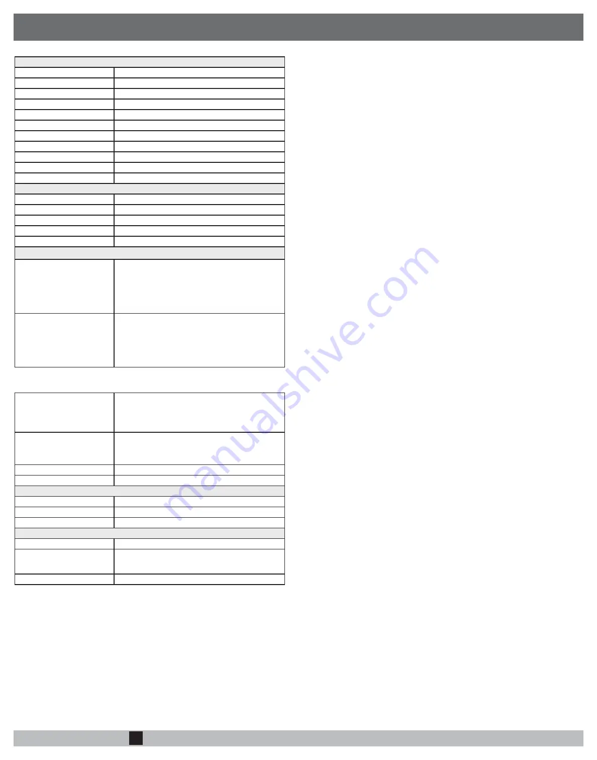
HIPswitch-100 Series
Ethernet Ports
2 x 10/100 Mbps on RJ-45 ports, auto MDI/MDIX
Power Input Failover
Automatic failover between all inputs
DC Power Input
Dual 12-48 VDC on terminal block
Power consumption
5W, typical
Storage Temp range
-40° to 85° C (-40° to 185° F)
Operating Temp range
-20° to 70° C (-4° to 158° F)
Operating humidity
5% to 95%
Enclosure
IP-30
Dimensions
45mm W x 81mm D x 95mm H (1.77” W x 3.19” D x 3.74” H)
Mounting
DIN-rail or wall-mount
Weight
410g (0.9 lbs.)
Power-over-Ethernet (PoE)
Operating Mode
IEEE 802.3at PoE PD
PoE Input Failover
Automatic failover between all three inputs
Protection Features
Overload and short-circuit protection
Isolation voltage
1000 VDC minimum
Isolation resistance
100 MΩ minimum
Cellular module (100g model only) – Supported Bands
4g Cellular Modes
LTE: 1900(B2)/ 1700(B4)/ 850(B5)/ 700(B13)/ 700(B17)/
1900(B25) MHz
Data rates: Category 3
Downlink: 100 Mbps (20MHz bandwidth), 50 Mbps (10 MHz
bandwidth)
Uplink: 50 Mbps (20 MHz bandwidth), 25 Mbps (10 MHz
bandwidth)
3g Cellular Modes
CDMA/EVDO rev. a/b: 800/1900 MHz
Data rates:
CDMA IS-856 (1xEV-DO Release A), Up to 3.1 Mbps forward
channel, Up to 1.8 Mbps reverse channel
CDMA IS-2000, Up to 153 kbps, simultaneous forward and
reverse channel
Circuit-switched data bearers up to 14.4 kbps
3.5g Cellular Modes
UMTS/HSDPA/HSUPA/HSPA+/DC-HSPA+: 2100(B1)/1900(B
2)/1700(B4)/850(B5)/900(B8) MHz
Data (HSPA+) rates:
Downlink: Up to 42 Mbps (category 24)
Uplink: Up to 5.76 Mbps (category 8)
2g Cellular Modes
GSM/GPRS/EDGE: GSM850/EGSM900/DCS1800/PCS1900
MHz
Data rates:
EDGE throughput up to 236 kbps
Cellular antenna connectors
Two SMA female connectors
SIM card slot
1 externally accessible
Serial Interface (-s models only)
Protocols
RS-232, RS-422, RS-485
Connector
DE-9M
Isolation voltage
2500 Volts minimum
Regulatory Approvals
EMI
FCC Part 15, CISPR (EN55022) class A IC ICES-003
EMS
EN61000-4-2 (ESD), EN61000-4-3 (RS), EN61000-4-4
(EFT), EN61000-4-5 (Surge), EN61000-4-6 (CS), EN61000-
4-8, EN61000-4-11
Safety
EN60950-1
SPECIFICATIONS


