

24
40-400-00001, Rev. A
Chapter 4: Simulator Operation
This section refers to the operation of the ILS-1000 in more detail. Many users of
the Simulator will not need to read this section.
When power is first applied to the Simulator, a self-test is performed and the inter-
faces are initialized. The front panel status LED will alternate between red and green
while performing the internal self-test. This takes about 30 seconds after which the
status LED turns to a solid green if the self-test passes successfully. Each interface
is continuously polled to determine if any devices are connected. The U-SYNC LED
is displayed when the initialization of the U port is complete. The S/T initialization is
done internally and its status is not shown by the U-SYNC LED.
The Layer 2
Data Link Controllers are then reset to the TEI Unassigned state and all
data link variables are set to zero. Finally, the Layer 3 Call Control database is
erased, Simulator configurations are loaded, and the Simulator waits for the arrival
of signaling packets on the D Channel.
When the Simulator is processing D Channel packet traffic in this way, the keypad’s
STATUS LED is illuminated a solid green, which signals that the Simulator’s ports
now offer ISDN-BRI services.
When simulation begins, any terminals or communications devices connected to the
Simulator must request TEI’s and establish Multiple Frame operation before they
can transfer Layer 3 Call Control packets to the Simulator. The first Call Control
Message sequence performed is usually the SPID initialization procedure for
acquiring an Endpoint ID.
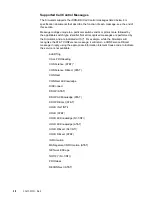
The Simulator performs ISDN-BRI Call Control using all essential Messages and
Information Elements defined for National ISDN-1and the AT&T 5E(option) series
switch.
NOTE: Layer 2 Disconnected Mode is supported only when initiated by
Terminating Equipment. Layer 1 deactivation and phantom power reverse polarity
are not implemented.
All functions of a circuit-switched call are performed, which includes applying in-
band tones and completing B Channel connections. D Channel X.25 Virtual Circuit
packet mode calls are also supported. Calls may be originated from either line
(called a Port) and may terminate at either line. Up to 10 end-to-end calls may be
placed simultaneously.
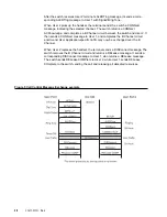
A diagram illustrating a typical end-to-end ISDN-BRI Call Control Message ex-
change is shown in Chapter 5.
When Call Control Messages are sent to or returned by the Simulator, the Message
type is displayed under the applicable Port and Directory Number.
Some terminals send a
Link Monitor Receiver Ready packet every 30 to 60 seconds
to confirm the integrity of packet operation during periods of inactivity. If simulation
is halted when this occurs, the terminal will attempt to restart the Simulator’s link
controller supporting that terminal. When simulation is continued, the Simulator
successfully renegotiates data links with most terminals attempting to do the same,
and operation resumes normally.


