


HARDWARE
Infinity Link Gateway Front Panel
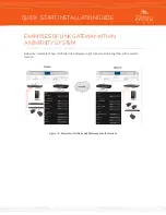
Figure 1: Front panel
PSU 1 LED (A) and PSU 2 LED (B)
The status of each power supply is shown on its respective LED. Green indicates proper operation. Red
indicates a fault. No LED indicates power is not being delivered to the supply from the mains source.
Status LED (C)
The Status LED is used to show a general fault in the hardware. Green indicates normal operation. Red
indicates a fault.
Sync LED (D)
When the Link Gateway locks to its reference clock, this LED will be solid green. A blinking green LED
indicates the unit is drifting from its reference to some degree, with more rapid blinking indicating more
jitter. If the unit cannot locate or sync to a reference signal, this LED will remain dark.
Front Panel LCD (E)
The color front panel LCD is used during initial setup and to display basic system information.
Navigation Cluster (F)
The navigation cluster consists of five keys: Left, Right, Up, Down, and OK. These keys are used during
initial setup and to change between system screens.
QUICK-START INSTALLATION GUIDE


