


6
2.2 Input wiring
For the inputs, the normally closed or normally open dry contact should be connected between
the given input (
IN1
…
IN4/IN6
) and the negative of the power input (
V-
) terminal.
If a normally open dry contact is used to activate the input, choose the
NO
(normally open) option
in the given input’s settings. In this case, the input will become activated when the open contact
between the given input (
IN1
…
IN4/IN6
) and the
V-
terminal becomes closed.
If a normally closed dry contact is used to activate the input, choose the
NC
(normally closed)
option in the given input’s settings. In this case, the input will become activated when the closed
contact between the given input (
IN1
…
IN4/IN6
) and the
V-
terminal becomes open.
2.3 Output wiring
The output provides normally open (N.O.) dry (potential free) relay contact by default and closed
contact upon control.
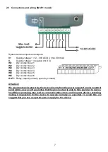
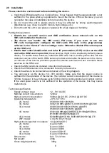
2.4 Connections and wiring (IN4.R2 model)
System terminal inputs and outputs:
V+
Supply voltage ~ /
12…30V AC/DC (min. 500 mA)
V-
Supply voltage ~ / negative (if DC)
IN1
Dry contact input 1
IN2
Dry contact input 2
IN3
Dry contact input 3
IN4
Dry contact input 4
OUT1
Relay output 1 (normally open dry contact)
OUT2
Relay output 2 (normally open dry contact)