

3
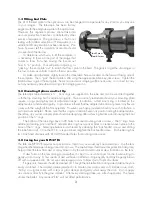
1.3 Tilting End Plate
The tilt of the end plate to the optical axis can be changed to compensate for any tilt errors you may see
in your images. The telescope has been factory
aligned with the end plate square to the optical axis.
However, this alignment process cannot take into
account production tolerances contributed by other
pieces of equipment. The good news is that in our
testing with random selections of FLI equipment, no
additional tilt compensation has been necessary. We
have, however, left this capability accessible should
you ever find it necessary.
To determine which way to tilt the end plate, it
is necessary to focus on the part of the image that
comes to focus first when moving the focuser out
from its “in” position. That will permit adjusting, or
“jacking,” the end plate “out” to match that focus point in the field. The goal is to get the star images in
the four corners as uniform to each other as possible.
To make an adjustment, slightly loosen the three Jamb Screws located on the forward facing side of
the end plate. Then, “jack” the end plate a little using the appropriate Allen key jack screws. Tighten the
Jamb Screws against the end plate. Some trial and error imaging will be necessary, so it is best to carry
out any necessary adjustments during a test imaging session.
2.0 Mounting Options and Set Up
The telescope tube diameter is 5”. Dual rings are supplied on the tube and can be used tied together
with the top mounting bar for additional rigidity. This bar is easily removable should your mounting plate
require a ring spacing beyond its adjustment range. In addition, a third mount ring is located on the
adapter tube to add extra rigidity. In practice we found that the adapter tube did not present any flexure
issues with the weight of the FLI equipment. However, we have provided it should you wish to fashion a
custom mount adapter. Please note that this ring must remain fixed in its position along the adapter tube.
Therefore, any custom adapter plate should be designing after achieving balance and knowing the final
position of the 5” rings.
The bottom of the tube rings have ¼-20 holes to accept mounting studs or screws. The 5” rings have
additional locating pins and the 4” adapter tube ring has a spacer block to create an even plane to the
base of the 5” rings. Telescope balance is achieved by unlocking the “bat handle” screws and sliding
the tube fore or aft. Once the O.T.A. is repositioned, retighten the bat handle screws. Each tube ring has
two machined channels with #10-32 threaded holes for mounting accessories.
3.0 Caring for your NP127fli
The Tele Vue-NP127fli requires no special care. Treat it as you would any fine camera lens. Use the lens
cap when the telescope is being stored or not in use. The captive dew shield provides protection from glare,
helps protect the lens from dust or spray blown in by the wind and minimizes dew formation on the lens.
If dew forms on the lens during cold weather, it is best to use a hair dryer (on the lowest setting) to
gently warm it away. A few specks of dust will have no effect on image quality and may be gently blown
off with a squeeze bulb. Do not use compressed air cans to blow dust off optical surfaces.
Fingerprints, however should be cleaned off. Though the anti-reflection coatings are durable, they are
easily scratched. The simplest cleaning method is to moisten (not soak) a very soft, lint-free tissue, cloth,
“Q-Tip” or surgical cotton with a lens or glass cleaner and gently whisk away the stain. Do not apply
any solutions directly to the glass surfaces. After every cleaning stroke, use a fresh applicator. The fewer
strokes the better! Any residual “film” will not affect performance.
Jack Screw
Jamb Screw