background image

Installation

1. 

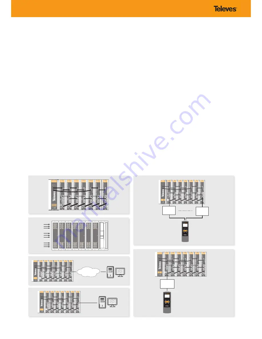
Install all units in the rack and connect them as shown in Figure 1.

2.  

The audio and video input signals connect to the back of the modules 

Figure 2).

3.  

If a network is available that provides IP addresses through DHCP, connect 

the encoders to the network as shown in Figure 3. If such a network is not 

available, then a computer will need to be connected as shown in Figure 

4.

4.  

Power on the units.

5.  

Connect the programmer to each unit and set a unique number in the 

“# ID” field according to the order of installation of the units in the rack 

(Figure 5). 

6.  

Connect the programmer to a unit, usually the first one, and read the IP 

address (Figure 6).

      Each unit can work as a master controller for the other units. All units can 

be configured by connecting to only one.

7.  

If a network was connected in Step 3 then proceed to step 8. If not, set the 

address of you computer as follows:

IP value = 172.20.0.2

netmask = 255.0.0.0

gateway = 172.20.0.3

NOTE

 The default factory configuration of the units has an IP address in this 

range (it should be different for each unit). If a unit was ever provided 

an address before, manually or through DHCP, this unique address may 

no longer exist. Resetting to IP factory defaults, will return the original 

unique private address though.

8.  

In your web browser, enter the IP address from Step 6 as the URL.

      A login prompt will appear. By default the parameters are:

Login: encoder

Password: encoder

Instalación

1.  

Instale todas las unidades en el rack y conéctelas como se indica en la 

figura 1.


2.  

Conecte en la parte posterior de los módulos las señales de entrada de 

audio y video (Figura 2).

3.  

Si dispone de una red que proporcione una dirección IP mediante un 

servidor DHCP, conecte los encoders a la red como se indica en la fig 3. 

Si la red no está disponible, deberá usar un PC para la conexión como se 

indica en la fig. 4 .

4.  

Encienda las unidades.

5.  

Conecte el programador a cada unidad y asigne un único número en el 

campo “# ID” de forma que coincidan con el orden de las unidades en el 

rack (Figura 5). 

6.  

Conecte el programador a una unidad, normalmente la primera, y lea la 

dirección IP (Figura 6).

      Cada unidad puede funcionar como maestra controlando las otras. Se 

pueden controlar todas las unidades conectándose solo a una.

7.  

Si se conectó a una red en el paso 3, siga en el paso 8. Si no, establezca la 

dirección de su PC de la siguiente forma:

IP = 172.20.0.2

Netmask = 255.0.0.0

Gateway = 172.20.0.3

NOTA

 La configuración de fábrica por defecto de las unidades tiene una 

dirección IP en este rango (ésta debe ser diferente para cada unidad). Esta 

dirección única no existirá si la unidad fue programada anteriormente, 

manualmente o mediante DHCP. Reseteando la IP a valores de fábrica, 

recuperará la dirección original única.

8.  

Teclee en su navegador web la IP del paso 6 como dirección URL.

      Aparecerá un mensaje de login. Los parámetros por defecto son:

Login: encoder

Password: encoder

Fig. 1

Fig. 2

Fig. 3

Fig. 4

Fig. 5

Fig. 6

Содержание TOX Series

Страница 1: ...HDTV ENCODER MODULATOR Quad Composite to COFDM QAM EN Ref 563822 w w w t e l e v e s c o m QUICK INSTALLATION GUIDE GUÍA DE INSTALACIÓN RÁPIDA HDTV ENCODER MODULATOR Quad Composite a COFDM QAM ES ...

Страница 2: ......

Страница 3: ...señado para uso en interiores El equipo cumple los requerimientos del marcado CE CautionStatements 1 Read these instructions 2 Keep these instructions 3 Heed all warnings 4 Follow all instructions 5 Do not use this apparatus near water 6 Clean only with a dry cloth 7 Do not block any ventilation openings Install in accordance with the manufacturer s instructions 8 Do not install near any heat sour...

Страница 4: ...Channel 1 Entrada audio analógico L R Canal 1 3 CVBS input Channel 2 Entrada CVBS Canal 2 4 Analog L R audio input Channel 2 Entrada audio analógico L R Canal 2 5 CVBS input Channel 3 Entrada CVBS Canal 3 6 Analog L R audio input Channel 31 Entrada audio analógico L R Canal 3 7 CVBS input Channel 4 Entrada CVBS Canal 4 8 Analog L R audio input Channel 4 Entrada audio analógico L R Canal 4 Rear vie...

Страница 5: ... and encoding audio video Solo una de las entradas está bloqueada y codificando audio video OUTPUT Color Output mode Modo salida Comment Situación Solid green Verde fijo Normal Output RF channel is ON broadcasting audio video normal mode Canal RF de salida encendido transmitiendo audio video modo normal Slow blinking green Verde parpadeo lento Carrier wave null or muted Portadora nulo o silenciado...

Страница 6: ... By default the parameters are Login encoder Password encoder Instalación 1 Instale todas las unidades en el rack y conéctelas como se indica en la figura 1 2 Conecte en la parte posterior de los módulos las señales de entrada de audio y video Figura 2 3 Si dispone de una red que proporcione una dirección IP mediante un servidor DHCP conecte los encoders a la red como se indica en la fig 3 Si la r...

Страница 7: ...nt feature The Auto option will ask for confirmation since it will overwrite the settings of all units set in Step 5 and the ordering will likely not be as the units were placed in the rack Clicking on the unit name a new window is opened and show the unit settings summary La página Status Summary será la primera en aparecer Esta proporciona un resumen de todas las unidades instaladas en la red y ...

Страница 8: ...ition cursor in edit mode Disable edit mode Activarelmodoedición Posición del cursor en modo edición Desactivar el modo edición Change section Save parameters press and hold for 3 sec Cambiar sección Guardar datos pulse y mantenga pulsado 3 seg Change menu Modify value in edit mode Cambiar menú M o d i f i ca r valores en modo edición ...

Страница 9: ...15 Code Reed Solomon Spectrum Mode Normal Inverted Frequency Step KHz 250 COFDM Modulation format QPSK 16QAM 64QAM Guard Interval 1 4 1 8 1 16 1 32 FEC 1 2 2 3 3 4 5 6 7 8 Bandwidth MHz 6 7 8 Cell_id Editable Frequency Step KHz 125 166 PSI PARAMETERS Transport Stream ID Editable Original Network ID Editable Network ID Editable Logical Channel Number Editable NIT Version Manual Automatic SDT Versio...

Страница 10: ... 15 Código Reed Solomon Spectrum Mode Normal Invertido Pasos de frecuencia KHz 250 COFDM Formato de modulación QPSK 16QAM 64QAM Intervalo de guarda 1 4 1 8 1 16 1 32 FEC 1 2 2 3 3 4 5 6 7 8 Ancho de banda MHz 6 7 8 Cell_id Editable Pasos de frecuencia KHz 125 166 PARAMETROS PSI Transport Stream ID Editable Original Network ID Editable Network ID Editable Número lógico de canal LCN Editable Versión...

Страница 11: ......

Страница 12: ...www televes com ...

Отзывы: