TELEVAC MV2A Скачать руководство пользователя страница 4

1.4

Safety Information

1

INTRODUCTION

1.4

Safety Information

START BY READING THESE IMPORTANT

SAFETY INSTRUCTIONS AND NOTES

In these instructions the word “product” refers to the MV2A and all of its approved parts and acces-
sories. NOTE: These instructions do not and cannot provide for every contingency that may arise in
connection with the installation, operation, or maintenance of this product. Should you require further
assistance, please contact Televac at the email address found in the footer of this manual.

This product has been designed and tested to offer reasonably safe service provided in it is installed,
operated and serviced in strict accordance with these safety instructions.

These safety precautions must be observed during all phases of operation, installation, and service
of this product. Failure to comply with these precautions or with specific warnings elsewhere in this
manual violates safety standards of design, manufacture, and intended use of the instrument. Televac
disclaims all liability for the customer’s failure to comply with these requirements.

ˆ

READ instructions – Read all safety and operating instructions before operating the product.

ˆ

RETAIN instructions – Retain the Safety and Operating Instructions for future reference.

ˆ

HEED warnings – Adhere to all warnings on the product and in the operating instructions.

ˆ

FOLLOW instructions – Follow all operating and maintenance instructions.

ˆ

ACCESSORIES – Do not use accessories not recommended in this manual as they may require a
technician to restore the product to its normal operation.

The MV2A qualifies as a Safety Extra-Low Voltage (SELV) device. As such, it represents little to no
hazard concerning electrical shock or burns.

Do not substitute parts or modify instrument. Because of the danger on introducing addi-
tional hazards, do not install substitute parts or perform any unauthorized modifications
to the product. Return the product to Televac for service and repair to ensure that safety
features are maintained. Do not use this product if it has unauthorized modifications
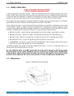
1.5

Dimensions

Figure 1: MV2A Dimensional Drawing

email: [email protected]

tel: +1 215 947 2500

web: frederickscompany.com

mv2a_im rev B

3 of 6

Содержание MV2A

Страница 1: ...2A Thermocouple Controller Instruction Manual The Fredericks Company Televac 2400 Philmont Avenue Huntingdon Valley PA 19006 web www frederickscompany com email sales frederickscompany com tel 1 215 947 2500 fax 1 215 947 7464 ...

Страница 2: ... 4 Calibration 5 2 4 1 Setting 1 mTorr Calibration Point 5 2 4 2 Setting 1 Torr Calibration Point 5 2 5 Analog Output 5 3 Part Numbers 6 List of Tables 1 Operating Specifications 2 2 Controller Cable and Sensor Part Numbers 6 List of Figures 1 MV2A Dimensional Drawing 3 2 MV2A Electrical Connection Information 4 3 MV2A Analog Output 5 email sales frederickscompany com tel 1 215 947 2500 web freder...

Страница 3: ...s relays and a 0 5 Volt analog output 1 3 Operating Specifications Table 1 Operating Specifications Operating Range 1 10 3 to 20 Torr Communications N A Programmable Set Points 2 Set Point 1 Relay Set Point 2 Relay Analog Output 0 to 5 V Linear Supply Voltage 90 V to 135 V AC 60 Hz Calibration Medium Dry air or nitrogen Overpressure Sensor dependent Analog Output Resolution 12 bits Operating Tempe...

Страница 4: ...s all liability for the customer s failure to comply with these requirements READ instructions Read all safety and operating instructions before operating the product RETAIN instructions Retain the Safety and Operating Instructions for future reference HEED warnings Adhere to all warnings on the product and in the operating instructions FOLLOW instructions Follow all operating and maintenance inst...

Страница 5: ...e sensor may affect accuracy and decrease the life of the sensor Exposure to oils and other contaminants will decrease the accuracy and decrease the life of the sensor Do not expose the sensor to corrosive gases 2 2 Electrical Information The MV2A has several connectors located on the rear of the unit A connection diagram is provided for convenience Figure 2 MV2A Electrical Connection Information ...

Страница 6: ...e holding the set point buttons press the Up and Down arrows until the MV2A reads 1 mTorr 2 4 2 Setting 1 Torr Calibration Point After setting the 1 mTorr calibration use the leak control on the vacuum system to adjust the pressure in the chamber until the reference gauge reads 1 Torr Then press and hold the SP1 and SP2 buttons on the MV2A While holding the set point buttons press the Up and Down ...

Страница 7: ... Male 2 2126 042 2A Sensor Stainless Steel 8 VCR Female 2 2126 043 2A Sensor Stainless Steel 4 VCR Male 2 2126 044 2A Sensor Stainless Steel 4 VCR Female 2 2126 045 2A Sensor Stainless Steel 1 33 CF DN16 ISO CF F 2 2126 050 2A Sensor Stainless Steel 2 75 CF DN40 ISO CF F 2 2126 052 3 ft Cable 2 9800 076 10 ft Cable 2 9800 077 20 ft Cable 2 9800 078 35 ft Cable 2 9800 079 50 ft Cable 2 9800 080 Vac...

Отзывы: