


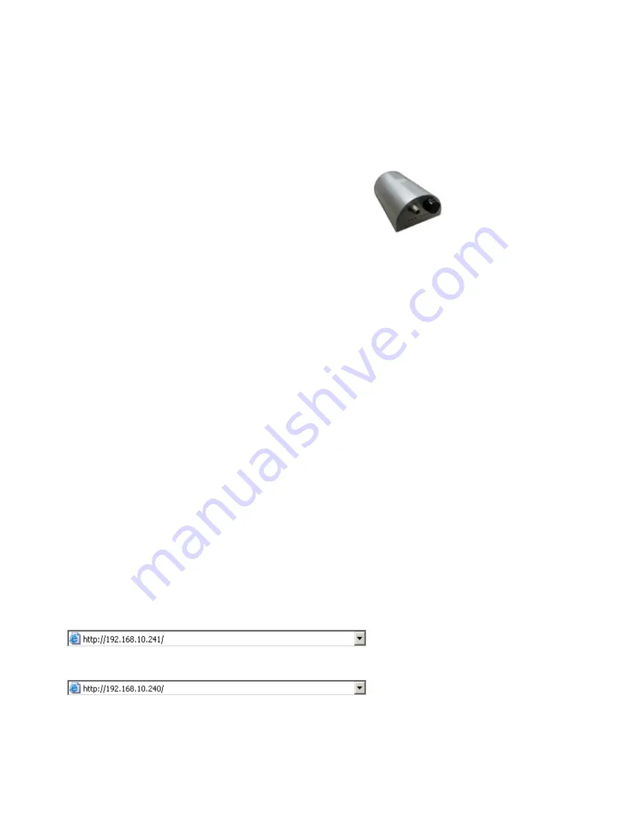
TT2400
Quick User Guide
802.11
g 223
mW
Package Contains
1. TT2400 802.11g PCBA (1)
2. IEEE 802.11g miniPCI radio card (1)
3. Power over Ethernet Injector (1)
4. 48VDC Power Adapter (1)
5. Ethernet Cable (2)
6. Waterproof RJ-45 Connector (1)
7. Mounting Hardware (1)
8. 6dBi Sector antenna,
9. 50cm RF cable (cable loss: 8dB)
10. User Manual
Quick Installation
Always double check for any missing parts from the kit you received before deployment.
Next step is to set up the computer Ethernet interface for configuring the TT2400. Since the default IP Address of the
unit is on the 192.168.10.x IP range in both Client Bridge and AP mode you’ll need to set the computer Ethernet
interface within the same IP range, such as 192.168.10.66.
Hardware Installation
Follow the procedure below to install your TT2400 device:
1.
Select a suitable place on the network to install the TT2400. For best wireless reception and performance the
external antenna should be positioned within Line of Sight from the AP with proper alignment.
2.
Connect the TT2400 to the ODU side of the PoE Injector via a straight Ethernet cable (Cat-5), and then connect
the NET side of the PoE Injector to either a computer or an Ethernet Switch.
Note: The TT2400 now fully supports the MDI/MDI-X standard and no longer require the use of cross over cable to
connect directly with a computer.
3.
Connect the 48VDC power adapter to the power jack on the PoE injector to power on the TT2400.
Check the LEDs on the TT2400 to confirm if the status is okay. At this point the
PWR
and
LAN
LEDs should be on
green. The
WLAN
light should light up once the unit is associated wirelessly with another wireless device. However at
this point the unit is still in factory default setting so do not the alarmed that the WLAN light doesn’t light up.
Web Control Interface
Default IP Address in Client Bridge Mode:
192.168.10.241
Default IP Address in Access Point Mode:
192.168.10.240
Default Login / Password:
Nothing needs to be typed in for login and password authentication.


