background image

11

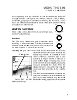
display. Soft bottoms such as
mud or sand appear as a thicker
line having a transition from dark
to light grays. Bottoms made up
of many rocks have a broken,
random appearance. 

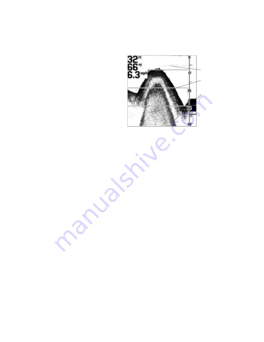
Bottoms having a large degree
of slope also present a unique
picture. These generally have a
thicker black band representing
the bottom directly under the
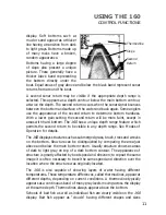
boat. Equal areas of gray above and below the black band represent sonar
returns from around the boat.

A second sonar return may be visible if the appropriate depth range is
selected. This appears as a depth contour below the main bottom contour,
at twice the depth. The second return occurs when the sonar signal bounces
between the bottom and surface of the water and back again. Some anglers
use the appearance of the second return to determine bottom hardness.
With a lower gain setting the second return will be more faint, except in
areas with hard bottom. The 

160

has a unique depth range feature which

permits the second return to be visible in any depth range. See Modes of
Operation for details.

The 

160

displays structure such as submerged grass, brush, trees and wrecks

on the bottom. Structure can be distinguished by comparing the area just
above and below the main bottom return. Usually structure shows as areas
of dark to light gray on top of a dark bottom contour. The appearance of
structure is greatly affected by boat speed and direction; to repeat the same
image it is often necessary to travel the same speed and direction over the
location where the structure was originally located.

The 

160

is also capable of showing layers of water having different

temperatures. These temperature differences, called thermoclines, appear at
different depths, depending on current conditions. A thermocline typically
appears as a continuous band of many gray levels moving across the display
at the same depth. Thermoclines always appear above the bottom. 

Schools of bait fish as well as individual fish are clearly visible on the 

160

display. Bait fish appear as "clouds" having different shapes and sizes

USING THE 160

CONTROL FUNCTIONS

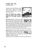
Thermocline

Slope

Second
Return

Содержание TFX160

Страница 1: ...TFX160 Operations Manual...

Страница 2: ...your Teleflex Sonar product Also to register your purchase and help us learn more about you please fill out the included warranty registration card WARNING This device should not be used as a navigat...

Страница 3: ...Performance 5 Simulator and Feature Memory 6 Control Functions 7 Knobs 7 Real Time Sonar Window 9 Chart Window 10 Modes of Operation 12 Automatic Mode 12 Bottom Lock Zoom Mode 14 Manual Mode 15 Contro...

Страница 4: ...es are designed with the same high standards and are backed by the same one year warranty All sonar accessories are available through your full service dealer or factory direct through our number list...

Страница 5: ...rea that has smooth water flow usually on the transom of the boat There are several mounting options for the transducer Review the following section to determine the method that works for you and your...

Страница 6: ...tion and operation on most boats However there are several situations which may require a different type of transducer Inboard boats wood or metal hulls and sail boats create unique transducer mountin...

Страница 7: ...minates confusion created by too many buttons and menus High technology high performance with back to basics operation makes the 160 the ideal choice of the serious angler The 160 uses sonar to locate...

Страница 8: ...of the 160 All controls are operational and settings can be changed to experiment with various features When operating in Simulator an indicator appears at the bottom left of the display There are tw...

Страница 9: ...on Press and hold GAIN to turn the unit off Increasing the gain shows faint sonar returns from small bait fish and suspended debris in the water however the display may become too cluttered in some wa...

Страница 10: ...for specific information In all cases turning the knob clockwise increases the range while turning it counterclockwise decreases the range Turning the knob slowly increases the adjustment in small in...

Страница 11: ...s from the bottom structure and fish that are within the transducer beam The RTS window updates with new sonar information much more quickly than the chart window up to 20 times per second in shallow...

Страница 12: ...th The width of the RTS window can be adjusted to your preference Selecting a wider RTS window shows greater differences between the strength of the sonar returns however it reduces the amount of hist...

Страница 13: ...e second return to be visible in any depth range See Modes of Operation for details The 160 displays structure such as submerged grass brush trees and wrecks on the bottom Structure can be distinguish...

Страница 14: ...that sonar cannot distinguish between a fish and some other object suspended in the water Regardless of the object the sonar detects each has the possibility of being drawn as an arch MODES OF OPERATI...

Страница 15: ...imum resolution follow these steps 1 Make sure the 160 is operating in Automatic Mode 2 Push the Range Knob An adjustment indicator appears at the lower right corner of the chart window 3 Turn the Ran...

Страница 16: ...y shows a full range view on right and a zoomed window on the left The zoomed window provides added display resolution for separating sonar returns that are very close together such as fish suspended...

Страница 17: ...acking leaving control of the depth range to the user Both the upper and lower depth ranges can be adjusted to show the bottom in great detail or any other desired depth When first switched to manual...

Страница 18: ...ent indicator disappears from the screen The 160 does not make adjustments to keep the bottom information on screen If the depth is deeper or shallower than the ranges on the display the bottom contou...

Страница 19: ...by a white background color 2 Rotate the CONTROL PANEL knob to select the desired option for adjustment Clockwise rotation selects options higher in the list counterclockwise rotation selects options...

Страница 20: ...lay back light and selects the brightness level The light is manually controlled except when the 160 first powers up During start up the back light turns on at full brightness so the display will be v...

Страница 21: ...d TVG Time Variable Gain to overcome surface clutter and counteract the affect of depth on sonar return strength The level 1 setting is optimal for making sonar information from all depths appear the...

Страница 22: ...per water The Depth Alarm can be muted by pressing the CONTROL PANEL knob once muted the alarm will not sound again until the boat moves to water greater than the Depth Alarm setting Remember depth is...

Страница 23: ...take some time to wet the transducer when returned to the water Small air bubbles can cling to the surface of the transducer and interfere with proper operation These bubbles dissipate with time or yo...

Страница 24: ...n simulator mode The 160 has the ability to detect that a transducer is connected If at power up a transducer is not connected the unit starts up in simulator mode Ensure that an appropriate transduce...

Страница 25: ...ay be the problem Be sure to include the transducer if returning the unit for repair 4 When in very shallow water I get gaps in the bottom reading and inconsistent digital depth indication The 160 wil...

Страница 26: ...d by other electronic devices Turn off any nearby electronics and see if the problem goes away Noise can also be caused by the engine If engine noise is causing the interference the problem will inten...

Страница 27: ...e Policy is valid in the United States only This applies to Teleflex Sonar units returned to our factory in Eufaula Alabama and is subject to change without notice All repair work is performed by fact...

Страница 28: ...Customer Support Hotline 1 800 747 9329 Throughout the U S and Canada hours are Monday Friday 8 15 a m to 5 00 p m Central time If after reading Troubleshooting you determine your unit needs factory s...

Страница 29: ...to Peak Area of Coverage 20 at 3 db Power Requirement 10 20 VDC Display 8 level FSTN Grayscale LCD LCD Matrix 160 H x 160 V Viewing Area 3 H x 3 V Mounting In dash or Gimbal Unit Size 4 V x 6 W x 2 D...

Страница 30: ...A Division of Teleflex Marine...

Отзывы: